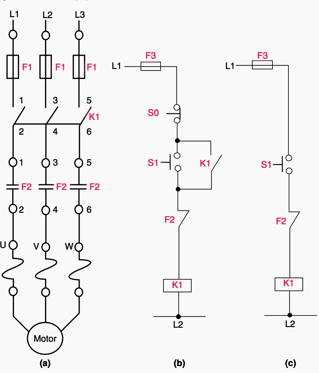
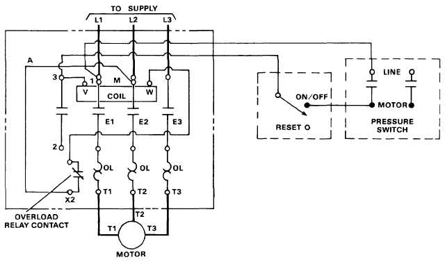
Single phase dol starter wiring diagram. The dol starter comprises of an mccb or circuit breaker contactor and an overload relay for protection.
Auto Transformer Wiring Diagram Motor Control Wiring
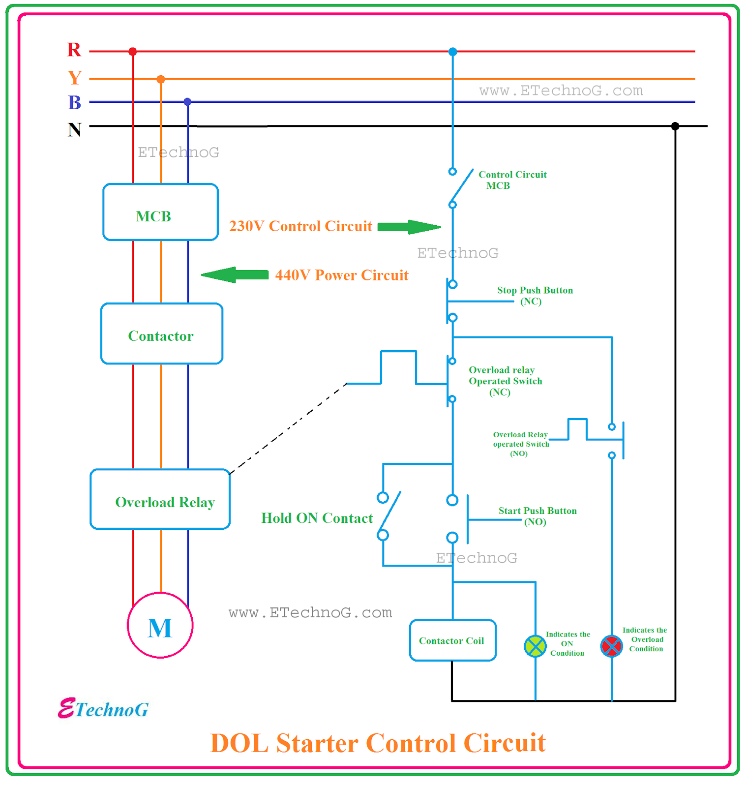
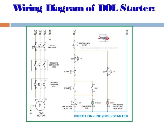
Dol motor control wiring diagram. We have to use all 3 poles of the overload relay otherwise the imbalance due to the current flow in only 2 of them will cause unnecessary tripping. In the above three. In the below dol starter wiring diagram i shown a molded case circuit breaker a magnetic contactor normally open push button normally close push button switch thermal overload relay motor trip indicator and 3 phase motor. A direct online starter consits of two buttons a green button for starting and a red for stopping purpose of the motor. The wiring diagram for a dol stater is shown below. I dol starter wiring connection with start and stop buttons are shown in the above figure 1.
This is the function of over current protective equipment like fuses and circuit breakers generally located in the disconnecting switch enclosure. A single phase dol motor starter can be designed using the same components as shown in following diagram. In this article we will discuss dol starter direct online starter working principle and construction dol starter diagram control diagram power circuit and wiring single 3 phase starter direct on line is the simplest and cheapest method used for starting three phase motor. Overload relays are employed on a motor control to limit the amount of current drawn. The overload relay does not provide short circuit protection. And one wiring is called controlling wiring.
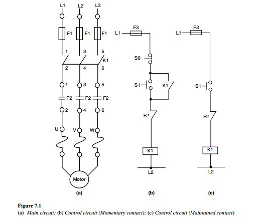
Wiring diagram of dol starter. One wiring called main wiring which is used for motor. Between the mains supply terminals and motor terminals the dol starter main terminals are connected and with the two terminals of the three phase power supply as described in figure 1 the control circuit is energized.

