Refrigeration and manufacturers wiring schematics also use diagrams b and c to ensure a positive troubleshoot ing application. Assortment of 3 phase motor starter wiring diagram pdf.

Square D Motor Starter Wiring Diagram H1 Wiring Diagram
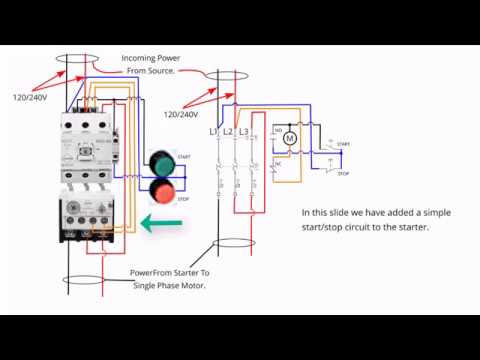
Single phase motor starter wiring diagram pdf. Motor 3ct to 120 v separate control ot is a switch that opens. Function of the single phase motor. Collection of single phase motor starter wiring diagram. M a1 a2 m. The start and stop circuits could alternatively be controlled using a plc. 13 17 with a flying lead to be connected to overload terminal 95.
The above diagram is a complete method of single phase motor wiring with circuit breaker and contactor. Thermal contacts tb white m 1 z2 yellow z1 blue u2 black u1 red bridge l1 and l2 if speed controller sc is not required m 1 ln e white brown blue l1 l2 n sc. Wiring of the direct on line dol motor starter 1 three phase supply 230volt coil see wiring diagram. Figure 17 3 shows a very basic one line diagram of the single phase motor. Single phase motor starter wiring diagram pdf a novice s overview of circuit diagrams. Diagram dd6 diagram dd7 m 1 ln e diagram dd8 ln e l1 l2 l3 sc z1 u2 z2 u1 cap.
It shows the parts of the circuit as simplified shapes and also the power and also signal links in between the tools. 1 the following links are pre fitted to the starter. The function is the exact same. For all other single phase wiring diagrams refer to the manufacturers data on the motor. It uses a contactor an overload relay one auxiliary contact block a normally open start pushbutton a normally closed stop pushbutton and a power supply with a fuse. All other control and power connections have to be made by the installer.
This diagram is for single phase motor control. Literally a circuit is the course that allows power to. It reveals the parts of the circuit as simplified shapes and the power and signal links between the gadgets. In the above one phase motor wiring i first connect a 2 pole circuit breaker and after that i connect the supply to motor starter and then i do cont actor coil wiring with normally close push button switch and normally open push button switch and in last i do connection between capacitor. Properly connect a single phase motors to a three phase starter. Obtaining from point a to direct b.
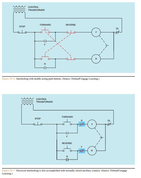
Single phase dwelling services101 table 12 awg and metric wire data 102 table 13 electrical formulas for amperes horsepower kilowatts and kva 103 table 14 ratings for 3 phase single speed. A wiring diagram is a streamlined conventional photographic representation of an electrical circuit. A wiring diagram is a simplified traditional photographic representation of an electric circuit. A very first look at a circuit diagram could be complicated yet if you can read a metro map you can review schematics. A2 14 18. Refer back to this diagram as the operational requirements of the single phase motor are discussed.
Gallery of Single Phase Motor Starter Wiring Diagram Pdf