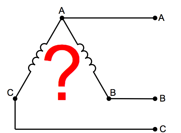
This connection proves to be economical for large low voltage transformers as it increases number of turns per phase. In this diagram a three phase unity pf load resistive load is supplied by two transformers.

Three Phase Y And Delta Configurations Polyphase Ac
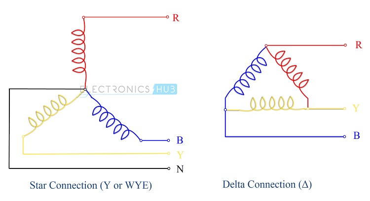
Delta connection diagram. For three phase motor we use the direct online starter but mostly for small three phase motor. The dashed lines indicate the transformer outlines. The delta delta connection of three identical single phase transformer is shown in the figure below. The diagonal of that parallelogram shows the vector difference of i r and i b which is equal to current in line 1 i 1. But high load 3 phase motor we use the star delta starter for motor. Line phase current and line phase voltage in delta δ connection.
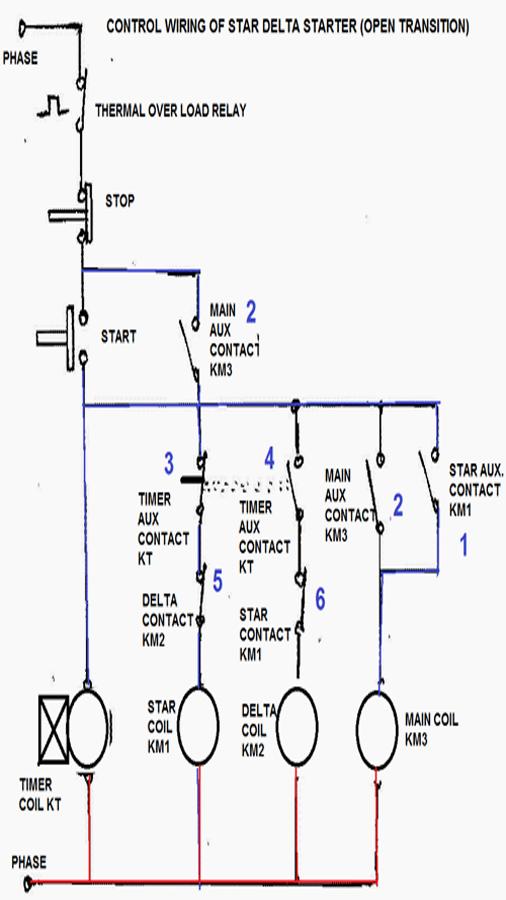
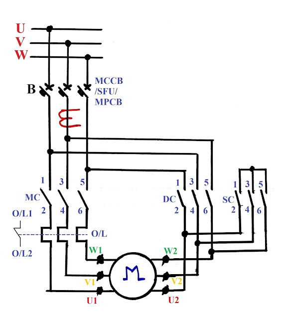
With each load resistance receiving 120 volts from its respective phase winding at the source the current in each phase of this circuit will be 8333 amps. Star delta starter wiring diagram this post is about the main wiring connection of three phase motor with star delta starter and control wiring diagram of star delta starter. The above figure shows the connection diagram of an open delta system. Hence in delta connection line voltage is equal to phase voltage. Connection diagram of open delta transformer. As in the balanced system the three phase current i 12 i 23 and i 31 are equal in magnitude but are displaced from one another by 120 electrical.
Transformer star delta connection diagram the phase voltage is lower than line voltage in star connection so the motors or drives connected in star connection runs at lower speed as compared to. The phasor diagram is shown below. Figure below the load on the δ source is wired in a δ. Primary side line voltage secondary side line voltage. The secondary winding a 1 a 2 is corresponding to the primary winding a 1 a 2 and they have the same polarity. Lets see how this works in an example circuit.
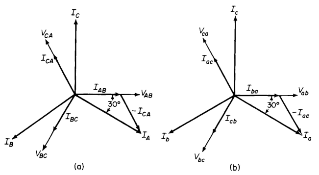
Advantages of the delta three phase. The polarity of the terminal a connecting a 1 and c 2 is same as that connecting a 1 and c 2. The current of line 1 can be found by determining the vector difference between i r and i b and we can do that by increasing the i b vector in reverse so that i r and i b makes a parallelogram. The connection diagram on the left shows how a deltadelta connection can be made either with three single phase transformers or with one three phase transformer. Delta connection example circuit analysis. Each transformer is rated as 10 kva current rating is 10 a and voltage rating is 1000 v.
Figure 2 phasor diagram of delta delta transformer connection. Relation between phase current and line current in delta connection. Primary side phase voltage secondary side phase voltage.


