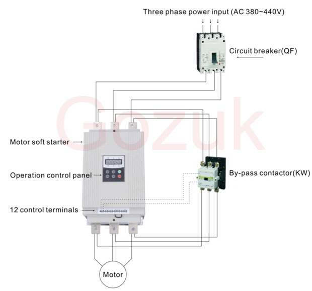
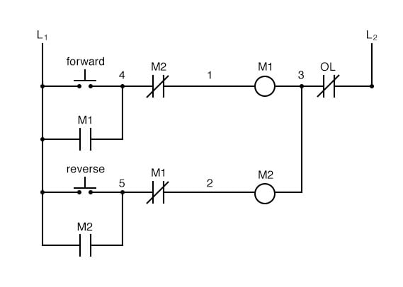
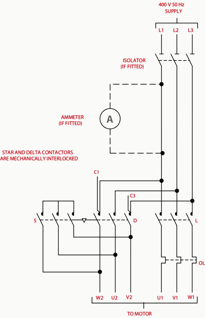
Large electric motors can be protected from overcurrent damage through the use of overload heaters and overload contacts. A contactor has three components.

Star Delta Starters Explained The Engineering Mindset
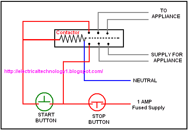
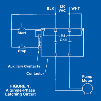
Contactor internal diagram. A simple circuit diagram either of the two start buttons will close the contactor either of the stop buttons will open the contactor. In the below magnetic contactor animation diagram is shown that the magnetic contactor coil are energized and the. Note that one one of the contactor acts as a switch for the start button. As contactors are used for high current load applications they are designed to control and reduce the arc produced when the heavy motor currents are interrupted. Magneticcontactor electricaltools tbelectricals magnetic contactor i internal parts explained. Use these tips to learn how to wire a contactor.
The electromagnet or coil provides the driving force to close the contactsthe enclosure is a frame housing the contacts and the electromagnet. These voltages must be electrically isolated from the standard 120 volts ac. Contactors use 120 volt standard power to energize a magnetic coil which causes a set of internal contacts to close and provide higher power to the equipment. Other than the low current contacts they are also setup with normally open contacts. Contactor wiring and i hope after this post you will be able to wire a 3 phase motor i also published a post about 3 phase motor wiring with magnetic contactor and thermal overload relay but today post and contactor wiring diagram is too simple and easy to learn. In the above magnetic contactor internal structure diagram the main contacts iron core coil and auxiliary contacts are shown.
The contacts are the current carrying part of the contactor. Contactors are used to provide this isolation. A contactor is a large relay usually used to switch current to an electric motor or another high power load. 2 days ago i wired 380 to 440 volts contactor for a 3 phase motor and save these images of contactor in pc. Its is important to. Enclosures are made of insulating materials such as bakelite nylon 6 and.
This is the first part of magnetic contactor animation diagram now lets move to the second diagram. Take a look at the diagram given below. This includes power contacts auxiliary contacts and contact springs.
