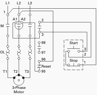
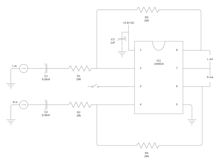
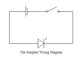
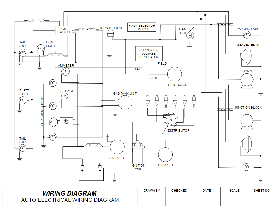
Unlike a block diagram or layout diagram a circuit diagram shows the actual electrical connections. They are crucial to the assembly of the circuit or system.
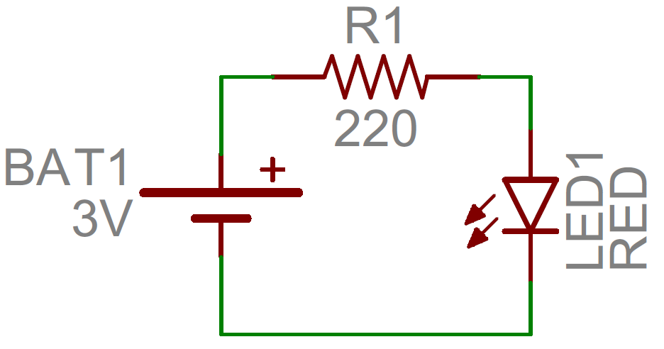
How To Read A Schematic Learn Sparkfun Com
Circuit drawings and wiring diagrams. A drawing meant to depict the physical arrangement of the wires and the components they connect is called artwork or layout physical design or wiring diagram. A diagram that represents the elements of a system using abstract graphic drawings or realistic pictures. It shows how the electrical wires are interconnected and can also show where fixtures and components may be connected to the system. Wiring diagrams or layouts illustrate the physical connections or wiring between components. Circuit diagrams are widely used for circuit design construction and maintenance of electrical and electronic equipment. Different types of electrical diagrams and drawing.
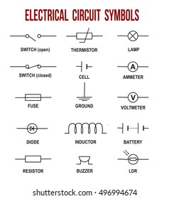
Electrician circuit drawings and wiring diagrams youth explore trades skills 3 pictorial diagram. In electrical and electronics engineering we use different types of drawings or diagrams to represent a certain electrical system or circuitthese electrical circuits are represented by lines to represent wires and symbols or icons to represent electrical and electronic componentsit helps in better understanding the connection between. A circuit diagram also named electrical diagram elementary diagram and electronic schematic is a graphical representation of an electrical circuit. Parts that are shown broken down into their sub components for the schematic retain their complete package format for the wiring diagram. A diagram that uses lines to represent the wires and symbols to represent components. Circuit diagrams can be divided into two categories pictorial circuit.
Circuit diagrams are used for the design circuit design construction such as pcb. A wiring diagram is a simple visual representation of the physical connections and physical layout of an electrical system or circuit.


