Oil level is at the designed limits. How to wire an electrical panel square d.
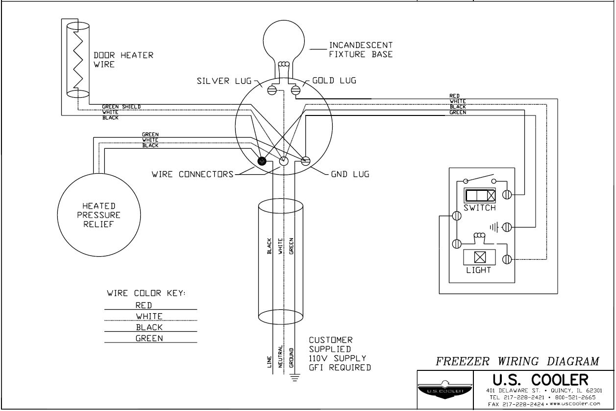
Technical Design Drawings U S Cooler
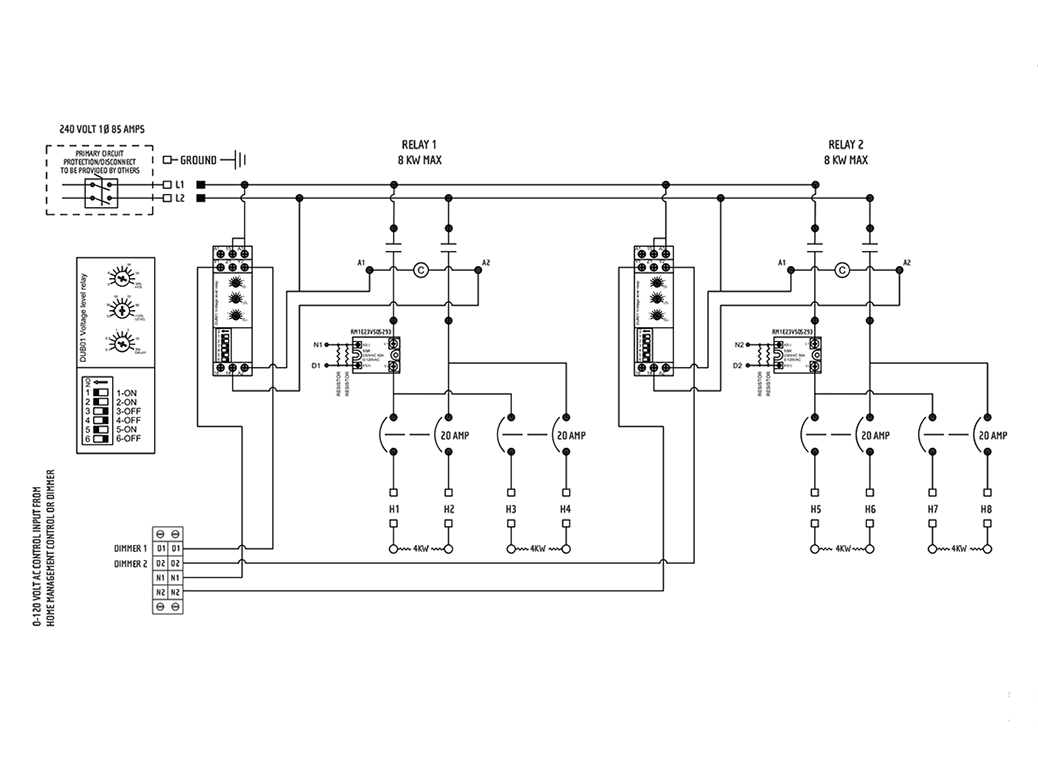
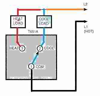
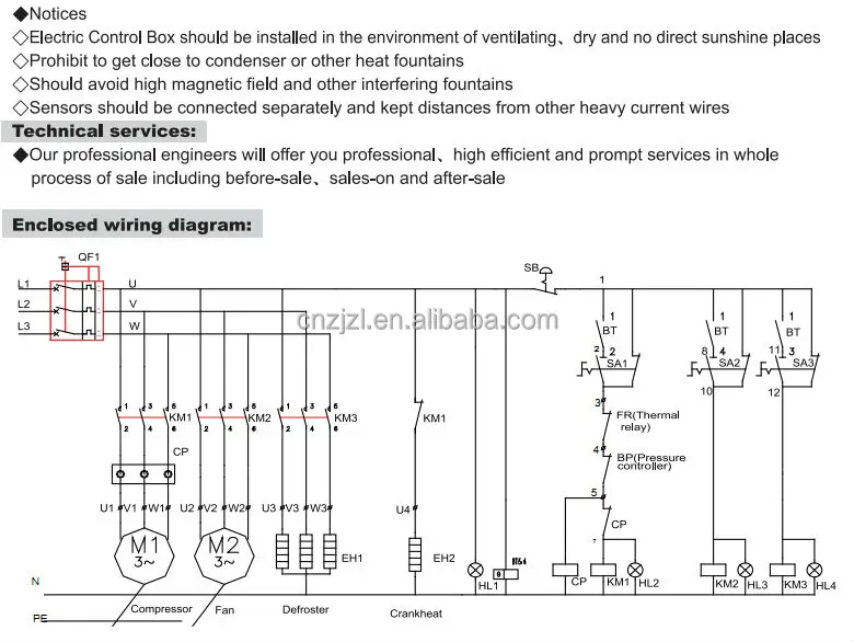
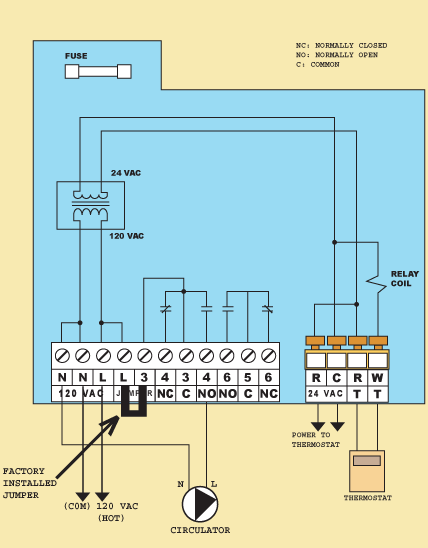
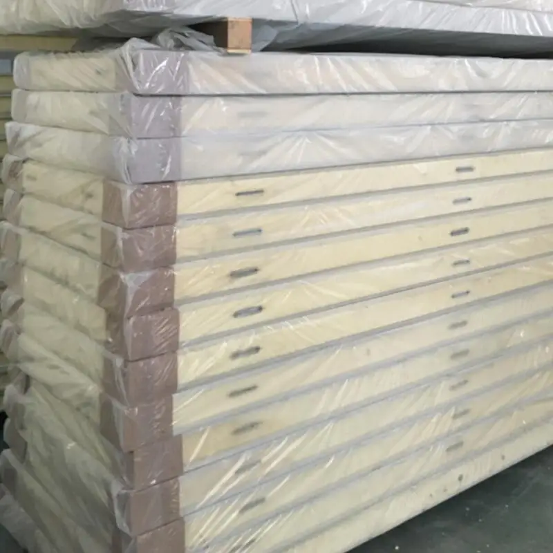
Cold room control panel wiring diagram. Mc cable is not a approved method for electrical wiring for a walk in cooler or freezer. It includes the entire panel ceiling panel and room panel which is made from import pipeline auto perfusion foaming import black material double side pressed colored steel panel with protective coating and the thickness is generally 100 mm 120 mm and 150 mm. Cold room ambient temperature range is 5c to 40c. Duplex pump control panel wiring diagram wire center. A wiring diagram is a streamlined traditional photographic representation of an electrical circuit. Sje rhombus wiring diagram gallery collections of rhombus wiring diagram warning light 4k wallpapers design.
It is a wall mounted control control panel dedicate to control the chiller and its various devices. The subzero nc 1000 are electrical control panel that integrate all the basic control functions required by a chiller. Duplex pump control panel wiring diagram wire center. A wiring diagram is a streamlined standard pictorial depiction of an electric circuit. Variety of cold room control panel wiring diagram. Evaporating unit only for complete cold room management.
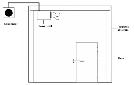
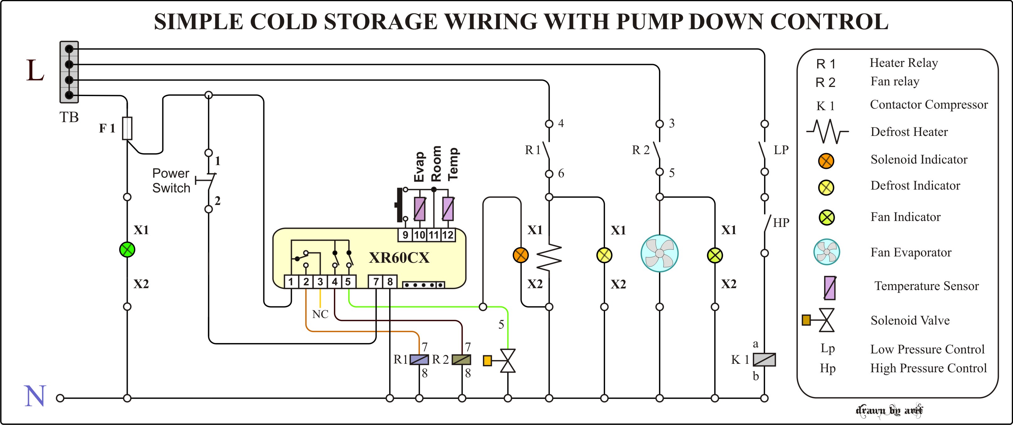
This type of wiring diagram has branch runs all shown as parallel circuits going from the left line l1 to the neutral line n. Franklin electric pump wiring diagram circuit connection diagram. General components of cold rooms. Front access to the automatic fuse and motor protector for the compressor and an. Thermostat and other control units of the cold storage room are properly set. Collection of terminal block wiring diagram.
True two door freezer not cold duration. A user friendly lcd screen displays all parameters status and alarm messages. It is the average box temperature that should be monitored not. Control panel freezer room cold room supply service cold room ripening chamber blast freezer scp cold shop no. It shows the elements of the circuit as streamlined shapes as well as the power and signal connections between the devices. 23 ransagar opp tulsi bungalows sardar.
Having completed the wiring please check with the wiring diagram to ensure it has been done correctly. If it was placed there the control would think that the whole box was cold and shut off the system as soon as it started. It shows the parts of the circuit as simplified shapes and the power as well as signal connections between the gadgets. On initial operation or restart after a long time the crankcase heater should be energized for 6 hours prior to start up.
