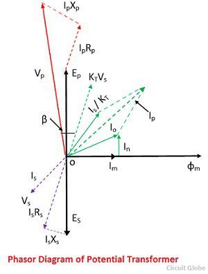
It is seen from the phasor diagram that the secondary phase voltage v an leads the primary phase voltage v an by 30. Connecting to 2 transformers so called v connection.
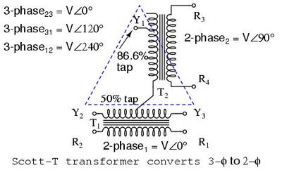
Scott T Transformer Wikipedia
3 phase potential transformer connection diagram. Connection diagram of open delta transformer. A three phase transformer is built for a specific connection and voltage transformation and the unit will have a nameplate with the internal connections shown. In this diagram a three phase unity pf load resistive load is supplied by two transformers. Primary connected between a phase and the earth. I need a 3 phase distribution transformer 10 15 kva to provide 120 volts power to appliances. Y y y y and.
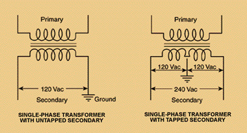
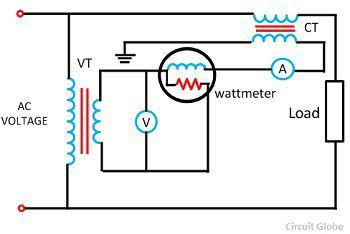
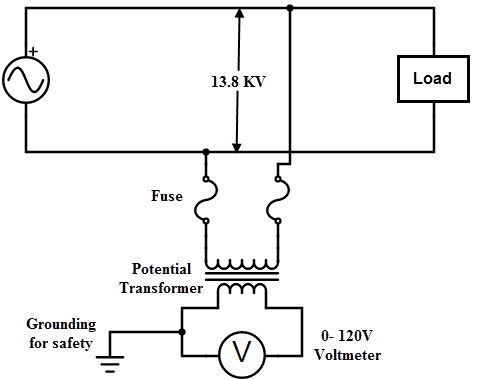
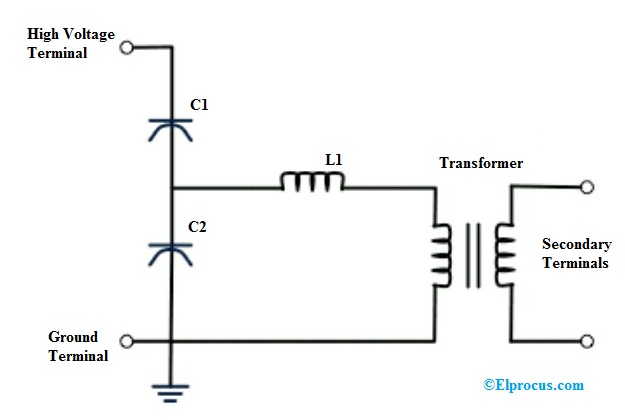
1 3 i l of the line current where i l is the line current. Requires 1 isolated mv terminal for each transformer. This transformer step down the voltage to a safe limit value which can be easily measured by the ordinary low voltage instrument like a voltmeter wattmeter and watt hour meters etc. What type of winding connection would be suitable y y d y y d or d d. Potential transformer pt definition the potential transformer may be defined as an instrument transformer used for the transformation of voltage from a higher value to the lower value. The four basic connections are.
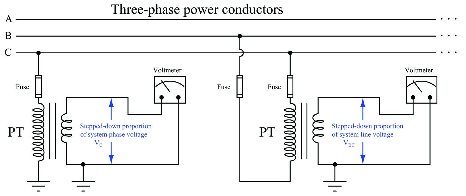
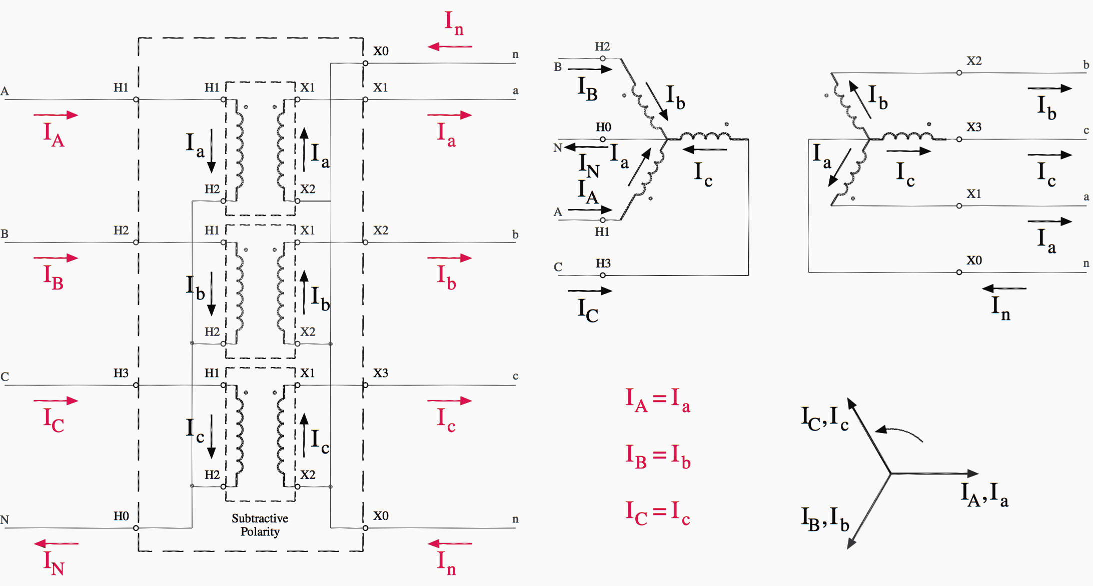
Id very much appreciate your expertise. In this case delta side will lead the wye side by 30 0. A method to test potential transformer polarity pt or vt is discussed and actual test results provided. Each transformer is rated as 10 kva current rating is 10 a and voltage rating is 1000 v. Three phase transformer connection diagram using this method is shown below. In this configuration the pt primaries and secondaries are both wired in wye.
The power available is 3 phase 240 volts line to neutral. This connection is incapable of furnishing a stabilized neutral and its use may result in phase to neutral overvoltage neutral shift as a result of unbalanced phase to neutral load. This is the preferred pt configuration because the meter will provide per phase voltage current power and energy readings for all three phases. The phasor diagram of the y connection of the three phase transformer is shown in the figure below. Delta closing type dab. Three wire wye service can be monitored with two different pt configurations.
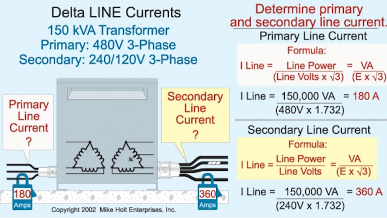
Requires 2 isolated. Metering connection arrangements for voltagepotential transformer star connection of 3 transformers. Three element pt wye output. In a delta connected dd group of transformers the line voltage v l is equal to the supply voltage v l v sbut the current in each phase winding is given as. Primary connected between two phases phaseearth. Monitoring a delta circuit.
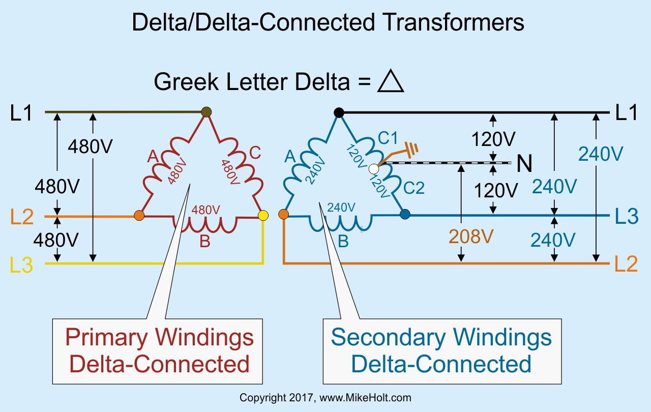
The above figure shows the connection diagram of an open delta system. The first symbol indicates the connection of the primary and the second symbol is the. One disadvantage of delta connected three phase transformers is that each transformer must be wound for the full line voltage in our example above 100v and for. Similarly v bn leads v bn by 30º and v cn leads v cn by 30ºthis connection is also called 30º connection. Basic connection of voltage potential transformer phasephase. When a single unit or bank of three is used there are four types of connections.
If a three phase unit is built on a three legged core the neutral point of the primary windings is practically locked at ground potential. The figure above shows a delta wye connection with dab connection.
Gallery of 3 Phase Potential Transformer Connection Diagram