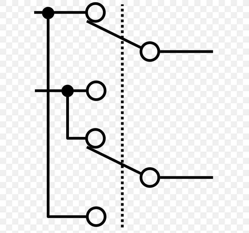
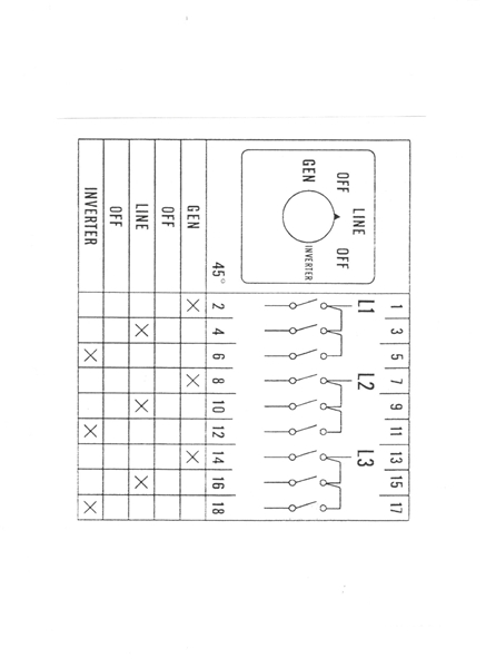
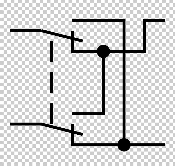
This circuit can be used for the automatic switchover of a load between a battery and a wall adapterltc4412 controls an external p channel mosfet to create a near ideal diode function for power switch over and load sharing. Manual changeover switch wiring diagram as you know that we use generator as emergency power source in our house wiring we can do the generator changeover system in two methods in which one is manual and 2nd one automatic system.
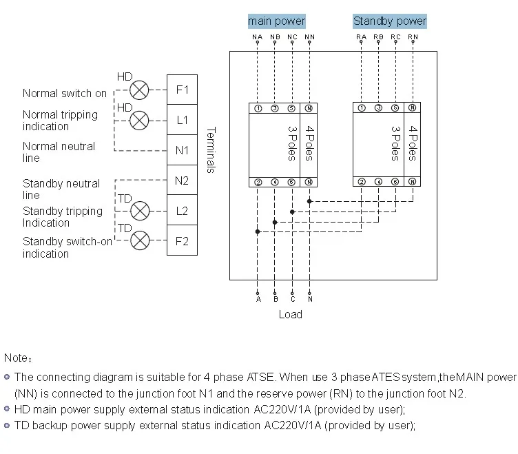
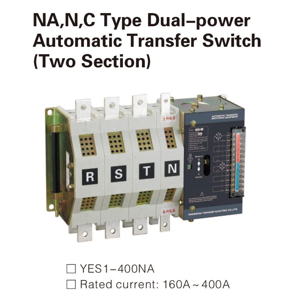
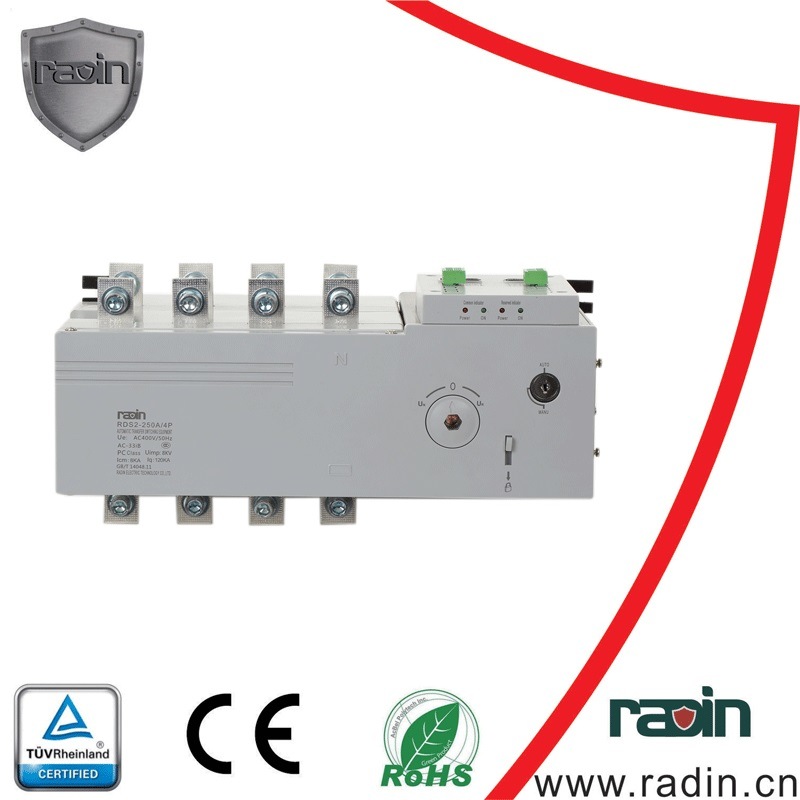
Yeq2y Automatic Changeover Switch For Generator Set Ats View Automatic Changeover Switch Yuye Product Details From One Two Three Electric Co Ltd
Changeover switch diagram. In this mode the timer output is either high or low depending upon the status of trigger and reset pin. Socomec technologies benefits fully compliant with iec 60947 6 1 power supply taken from an existing ups load shedding principle diagram. The circuit diagram shown here is of a automatic changeover switch using ic ltc4412 from linear technologies. A smart way to build an automatic changeover switch is by using a motorized changeover together with be28 ats controller. The timer output is connected to a transistor which acts as a switch being on or off depending upon the timer output. Compatible with abb eaton socomec motorized transfer switches.
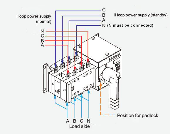
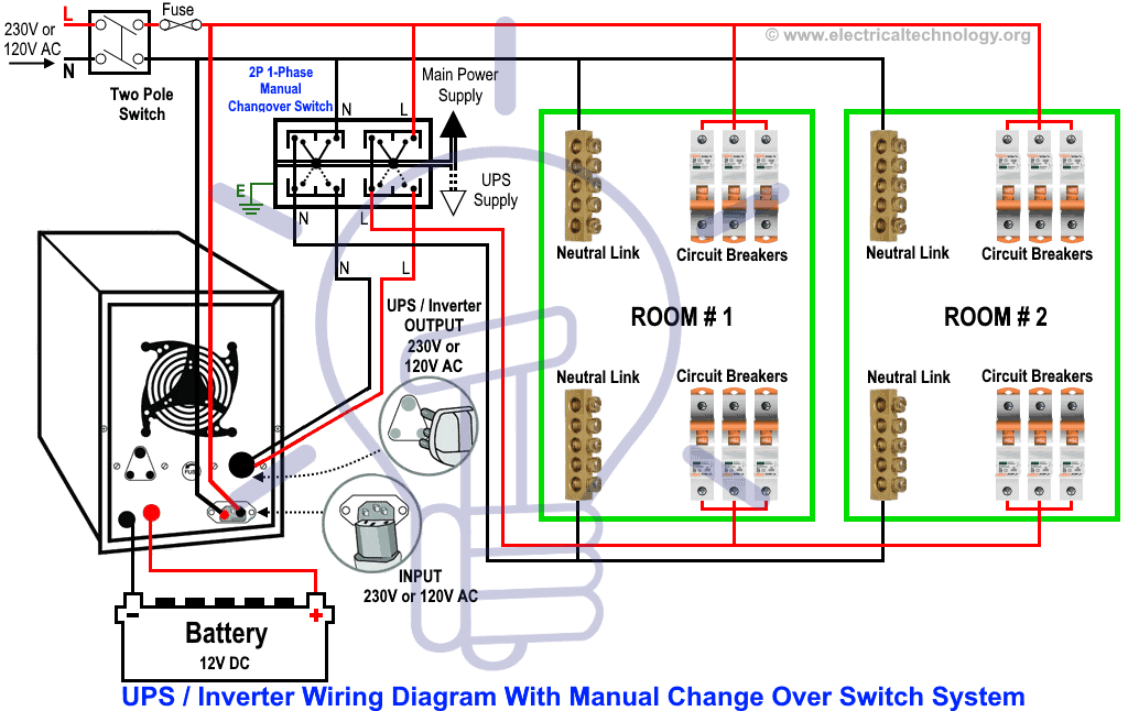
Ups 230vac critical loads non critical loads. It is also shows the working and operation for different changeover switches wiring connections like single phase manual changeover switch with generator three phase manual transfer switch connection with generator as well as single phase and three phase automatic transfer switches connections to the 1 and 3 phase generators and main fuse board. Automatic changeover switch for generator circuit diagram. A complete guide about wiring and installation about the rotary changeover rotary cam transfer switch for single phase 3 phase system with main supply and generator supply and load connection. How to do manual auto ups inverter wiring with changeover ats switch. In our previous ups inverter wiring diagrams connections for home we show that how to wire and connect an automatic ups and batteries to the home distribution board for continues power supply.
This circuit is based on the principle of bistable mode operation of 555 timer. Atys p associated to an inputoutput module can deliver a signal to the motorised switch in order to realise the load shedding. In today ups inverter installation tutorial we will show how to connect and install the battery backup power through. Automatic changeover switch circuit principle. A typical case study is presented in 11 from the literature 12 used cmos ics to design an automatic power changeover switch with emphasis only on power transfer between sources. What is an automatic transfer switch and how does it work.


