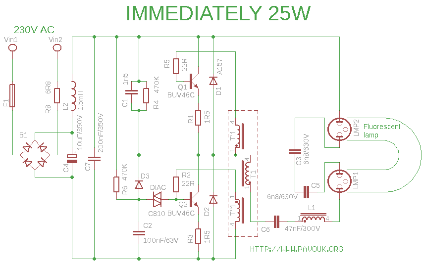
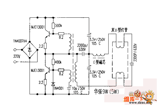
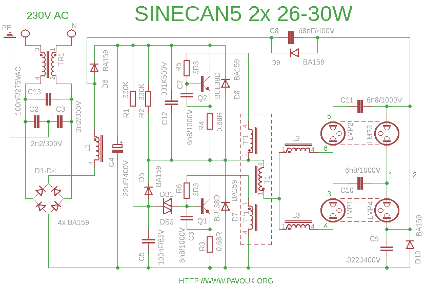
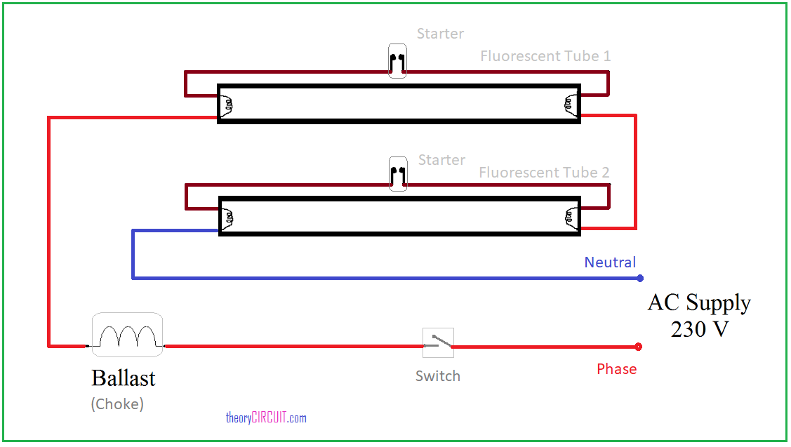
The function of choke is to provide high voltage enough for ionization to take place in a tube light and after establishment and substenance of ionization limit the voltage across the tube. Wiring diagram here two tube lights are used in our case each one is 20 watts each tube light will have.
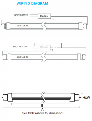
Forest Lighting Univ8 Ledt8 Tubes With Ballast Or Without
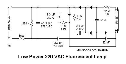
Tube light choke wiring diagram. Here is one example of a tube light fixture consisting of a large heavy square choke or ballast and a small cylindrical starter lets try to understand how the whole system works. For me 5 years tube and choke was v good. Please refer to the circuit diagram on the right as you read the following points. A wiring diagram is a simplified standard pictorial representation of an electrical circuit. After 5 years only i need to change one filter capacitor. I have added 47 5 w resistor instead of bulb.
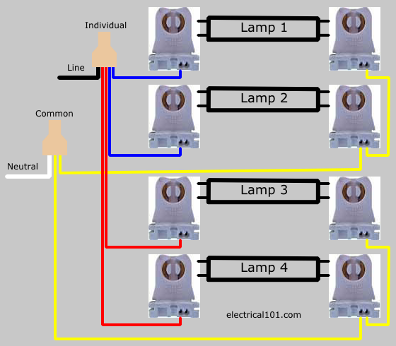
This article gives a details about double tube light connection by using single ballast or choke some electronic choke not support this connection check the ballast specification and watts level before make this type of connection. From the junction box the neutral wire is not taken out to the switch board rather it is taken out from the junction box and carried out to the port 2 of the tube light as per figure above. It shows the parts of the circuit as streamlined forms and also the power and signal connections between the gadgets. The starter is like a key of fluorescent light because it is used to light up the tube. Assortment of t8 led tube light wiring diagram. No power will be run to the other end the diagram below is for single end led t8 ballast bypass lamps.
Hence ordinary tube with electronic. Tube lights are most used light source and here tube light connection circuit and wiring diagram given with explanation. Due to heat its electrolyte dried up. So the neutral wire is continued from port 2 to pin 1 of terminal 2. Led also lasts only for say 2 years. This is shown in the following image which features the led tube light connection diagram.
Rajput technical 1214785 views. How to check tube light choke starter capacitor cfl bulb soldering iron by using series test duration. How to install a single tube light with electromagnetic ballast. After that its pcb will give problem. A wire already connects port 2 and pin 1 of the terminal 2. When we connect the ac supply voltage to the circuit then the starter act like short circuited and current flow through those filament located at the first and second end of the tube light and the filament generate heat and it ionized the gas mercury vapor in the fluorescent tube lamp.
For this application of fixtures for tube lights one socket will have the live power and the other socket will serve solely as a lamp holder. The tube light or fluorescent light is a low pressure mercury vapor gas discharge lamp and it uses fluorescent to produce white light. Wiring of flourescent lights. Hence calculation of turns is the major work. The choke is in fact a large. Connection of tube light is very simple because it has few wiring points only.

