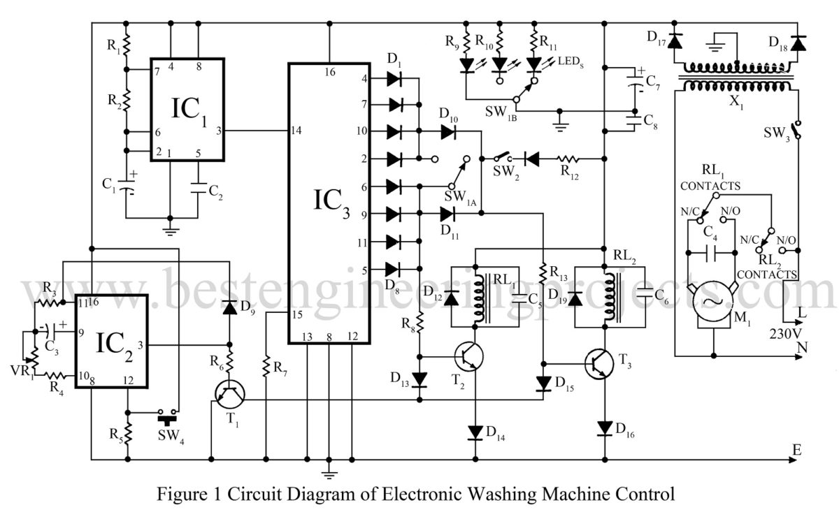
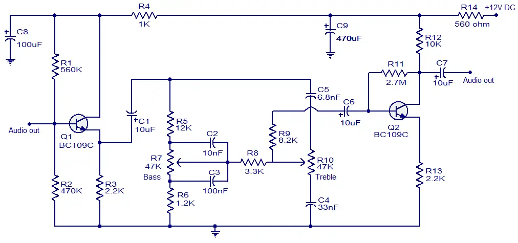
They are an ideal means for troubleshooting a circuit. See more ideas about electrical diagram electrical circuit diagram electrical engineering.
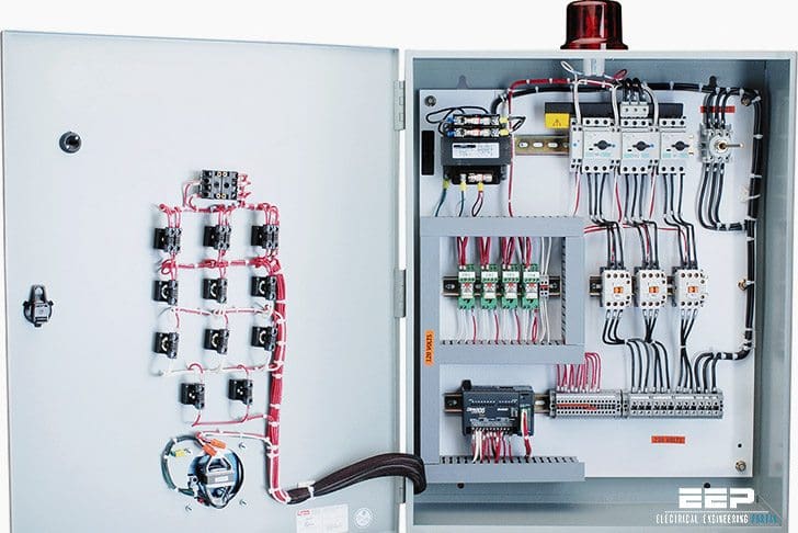
Basic Wiring For Motor Control Technical Data Guide Eep
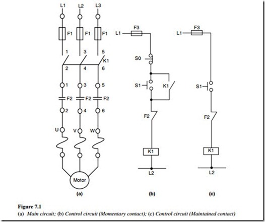
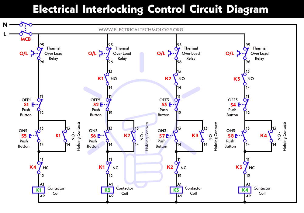
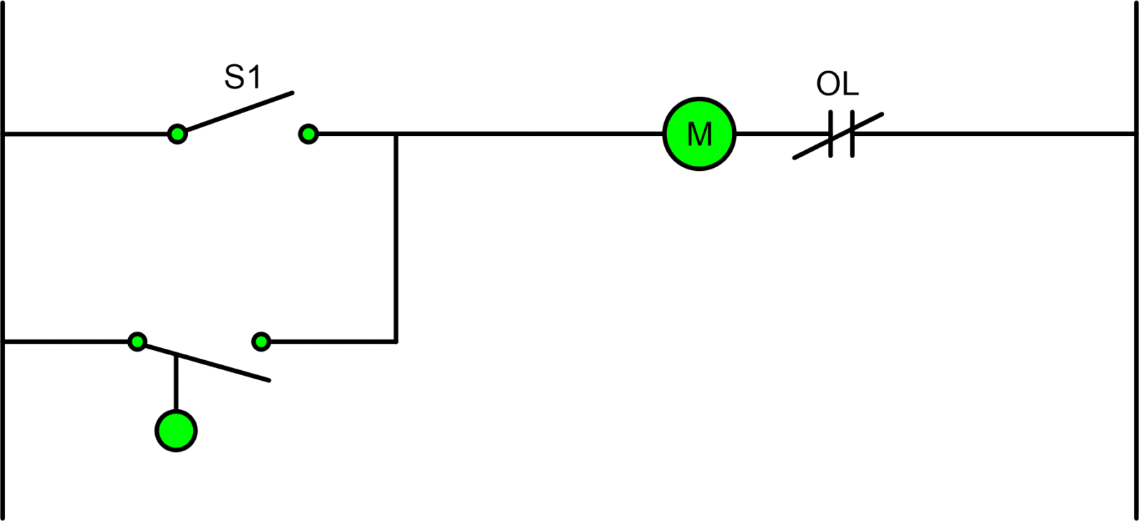
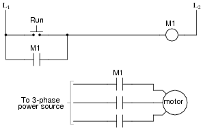
Basic control circuit diagram. 3 schematic diagram of the circuit shown in ill. Jun 30 2020 explore juni joness board circuit diagram on pinterest. Two wire control circuits and three wire control circuits. A very common form of latch circuit is the simple start stop relay circuit used for motor controls whereby a pair of momentary contact pushbutton switches control the operation of an electric motor. See more ideas about circuit diagram circuit electronics circuit. A two wire control circuit can be a simple switch that makes or breaks connection to a motor figure 18 1.
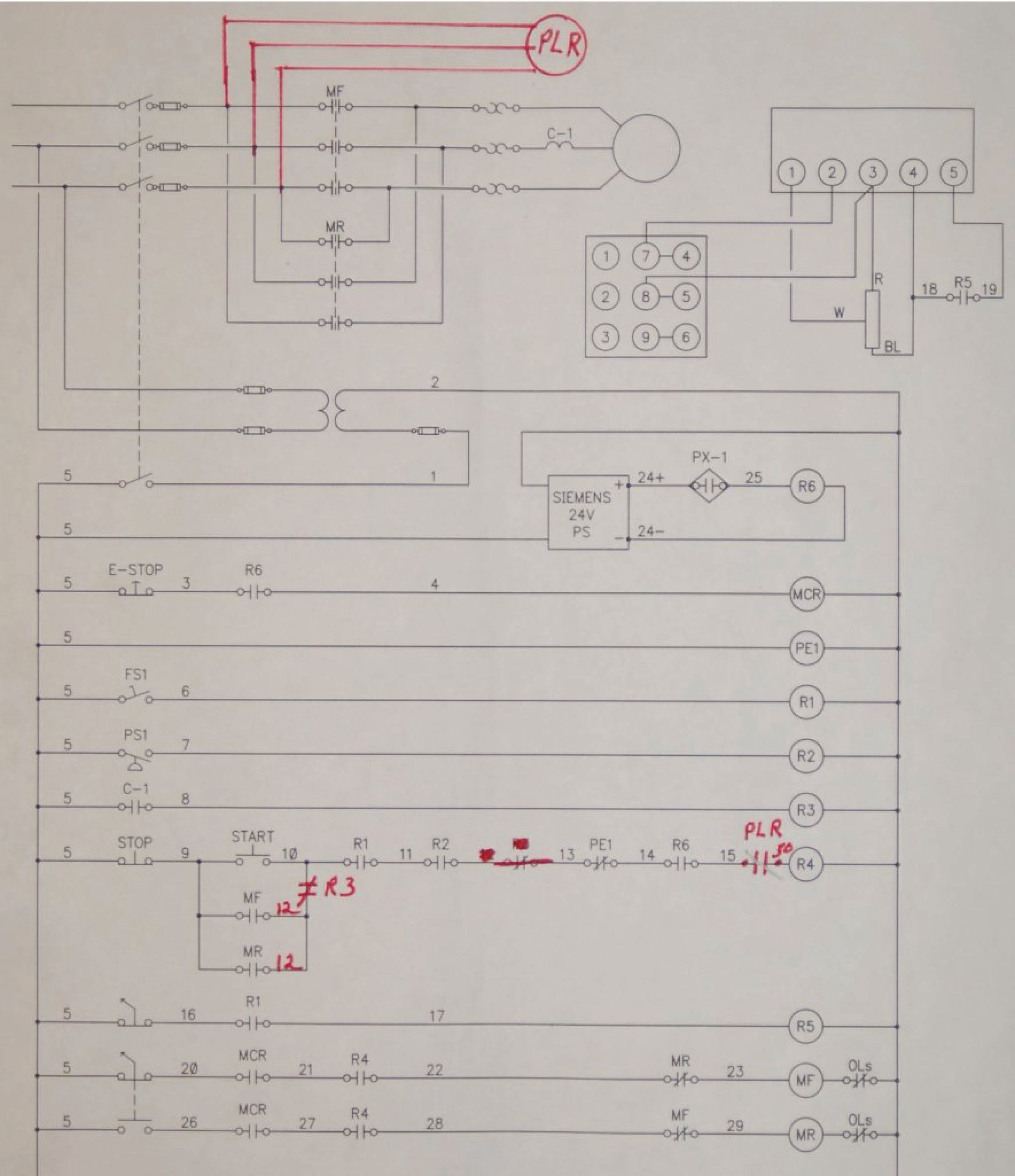
A two wire line voltage control circuits shown in ill. Control circuits can be divided into two major types. They do not indicate the physical relationships of the various components in the controller. A good example of this type of control is the single phase manual starter shown in figure 3. Feb 5 2020 explore elects agass board electrical diagram on pinterest. Line diagrams also called schematic or elementary diagrams show the circuits which form the basic operation of the controller.
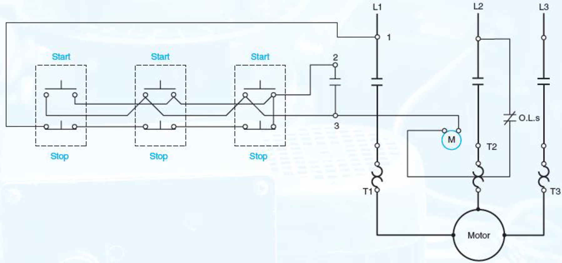
In this particular case i show a low voltage control circuit and a 3 phase higher voltage motor. Figure 2 shows a typical line or schematic diagram. Three wire control circuits are characterized by the use of momentary contact devices such as push buttons.
