Use this 4 pin trailer wiring diagram to properly wire your 4 wire trailer plug. Each component ought to be set and connected with different parts in particular manner.
Trailer Wiring Diagram And Installation Help Towing 101
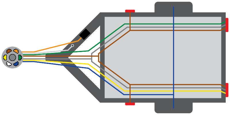
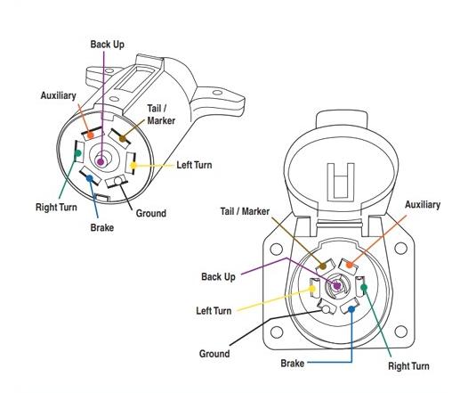
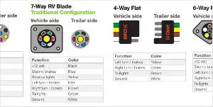
Standard 7 wire trailer wiring diagram. The four wires control the turn signals brake lights and taillights or running lights. 4 way trailer connectors are. 7 way wiring diagram for colors yellow white red green blue brown and black. Some vehicles use a combination bulb dual filament for turn and stop. Car trailer wiring diagram uk new best ford 7 way trailer plug. If not the arrangement will not function as it ought to be.
7 way trailer plug wiring diagram gmc wiring diagram collection. Wiring a 7 way trailer connector if existing wire colors dont match. Tow vehicle has same bulb for lighting stop and turn signals. Blue electric brakes or hydraulic reverse disable see blue wire notes below in the trailer wiring diagram and connector application chart below use the first 5 pins and ignore the rest. 7 way trailer plug wiring diagram ford collections of wiring diagram rv 7 way plug refrence 7 wire trailer wiring diagram. Use a simple 4 way flat connector to power your 2 light trailer lights or use a custom vehicle specific trailer wiring harness.
Use the 7 pin connector anyway see below and just leave out the last 2 wires. As the name implies they use four wires to carry out the vital lighting functions. 7 way trailer connectors are used by the following vehicle types. 7 pin trailer wiring diagram with brakes. How to install 7 way metal trailer connector and wiring harness for a 1999 jeep wrangler. Tow vehicle taillight wiring 2 wire system.
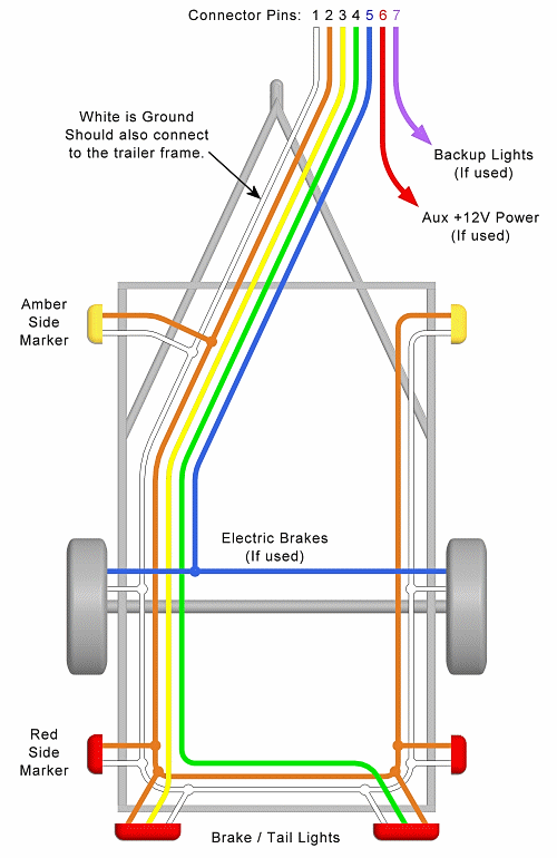
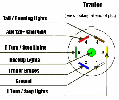
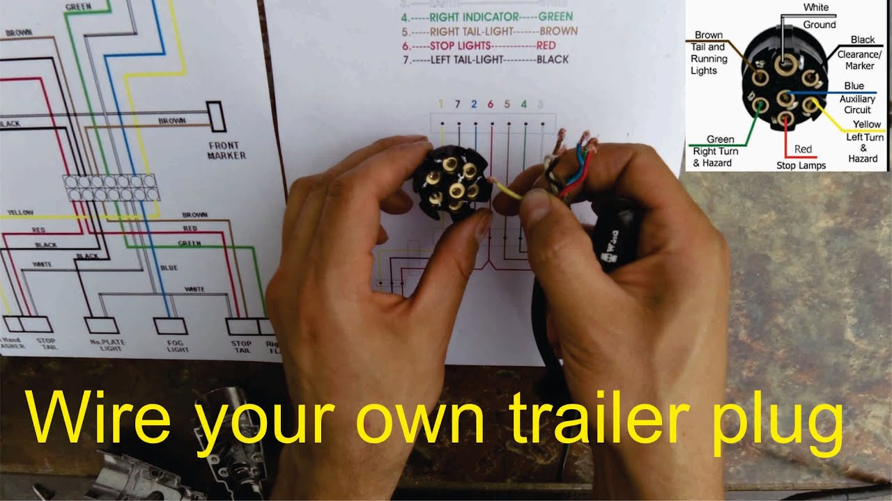
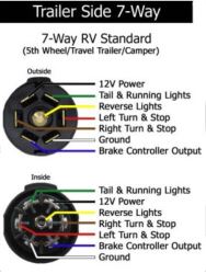
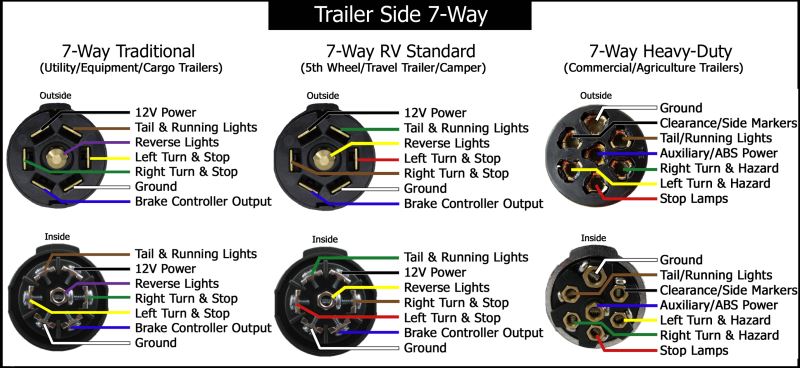
Wiring in bed trailer wiring 12 volt power to a switched ignition source on a 2004 chevy silverado. Wiring diagram for ifor williams trailer lights best ifor. Following the standard method for wiring a trailer connector is vital to the safety of your vehicle while towing. 7 way trailer wiring diagram is explained in details in the picture and the table below. 7 way plug wiring diagram standard wiring post purpose wire color tm park light green battery feed black rt right turnbrake light brown lt left turnbrake light red s trailer electric brakes blue gd ground white a accessory yellow this is the most common standard wiring scheme for rv plugs and the one used by major auto manufacturers today. Large 5th wheel trailers.
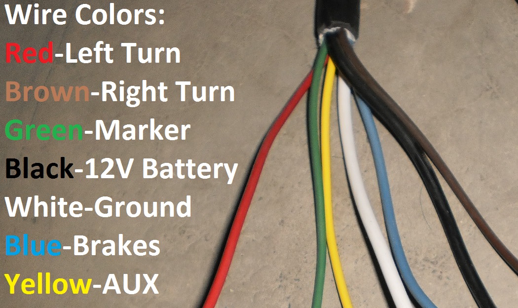
Converter for use with vehicles that have separate turn and brake light wires. 7 pin trailer wiring diagram with brakes 7 pin flat trailer wiring diagram with brakes 7 pin rv trailer wiring diagram with brakes 7 pin trailer wiring diagram with brakes every electrical arrangement is made up of various different parts. They also provide a wire for a ground connection. If your truck has a built in 7 pin socket but you only need 5 of the pins. Connecting the wrong color wires will result in mismatched taillight functions and confusion on the road. On most recreational vehicles.
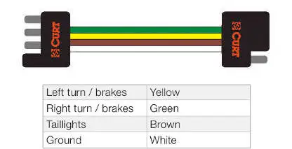
Some vehicles send only one signal per wire. Standard 4 pole wiring harness for use with vehicles that have adequate power and standard wiring system these simply connect into existing wires on the vehicle and have a 4 pole flat connector to attach a trailer. 4 way trailer connectors are typically used on small trailers such as boat snowmobile utility and other trailers that that do not use brakes.
Gallery of Standard 7 Wire Trailer Wiring Diagram


/trailer-wire-colors-589d62645f9b58819cf8721f.gif)