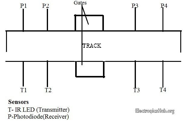
Circuit 2 automatic railway gate controller with high speed alerting system. K1 auxiliary relay open k3 auxiliary relay close k2 timer contactor relay k4 timer contactor relay.

Pdf Automatic Railway Gate Control System Using 8051micro
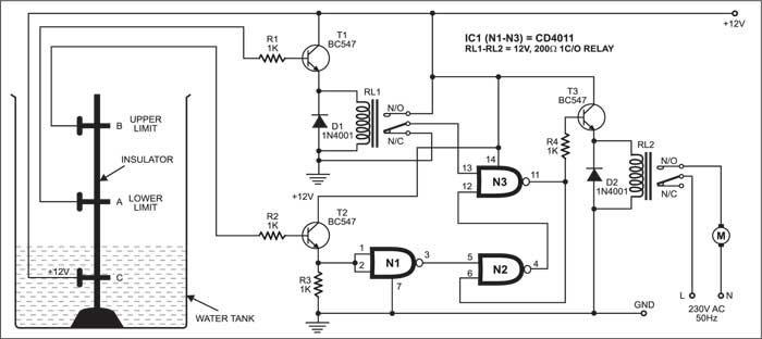
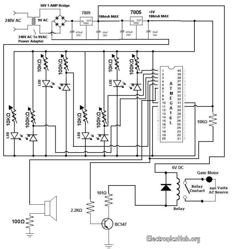
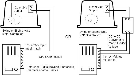
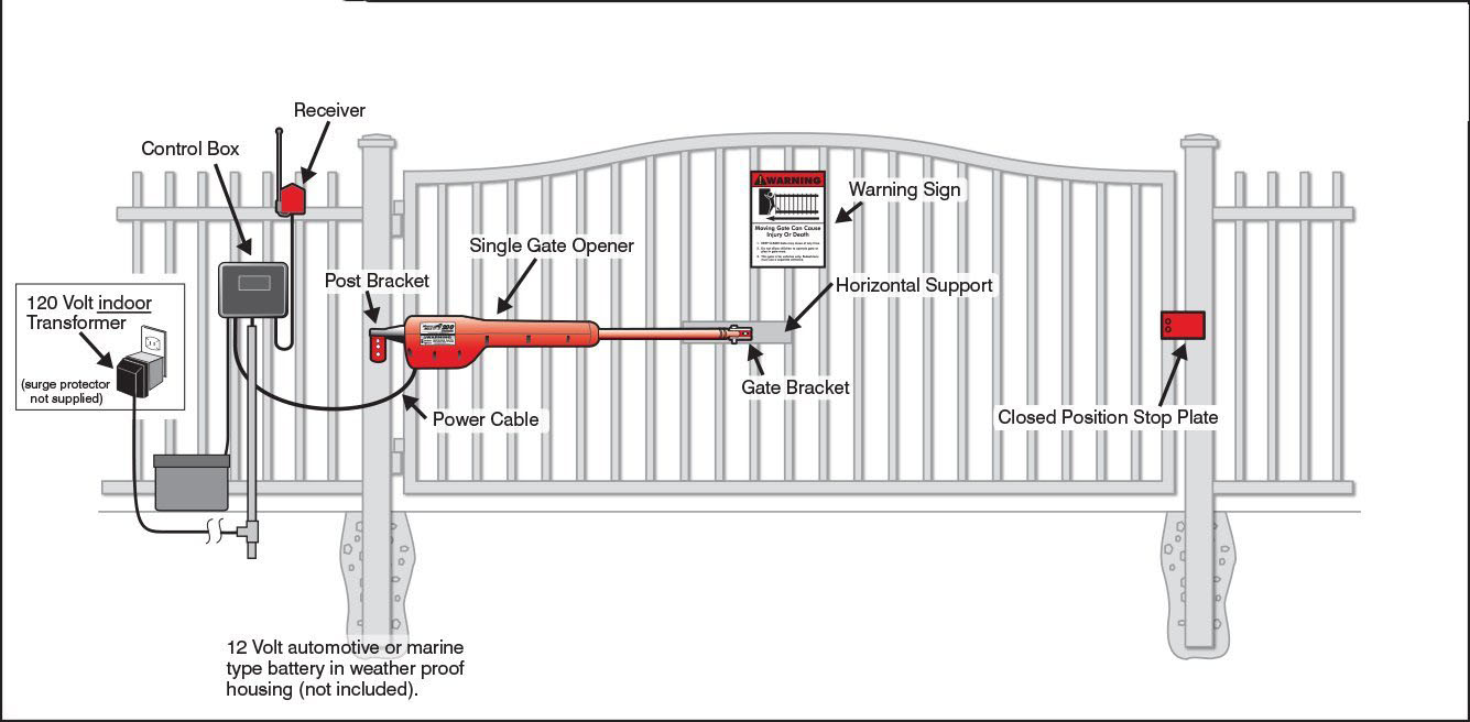
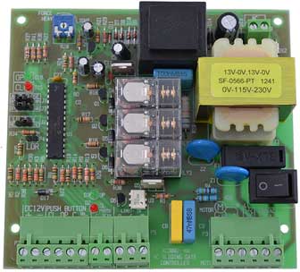
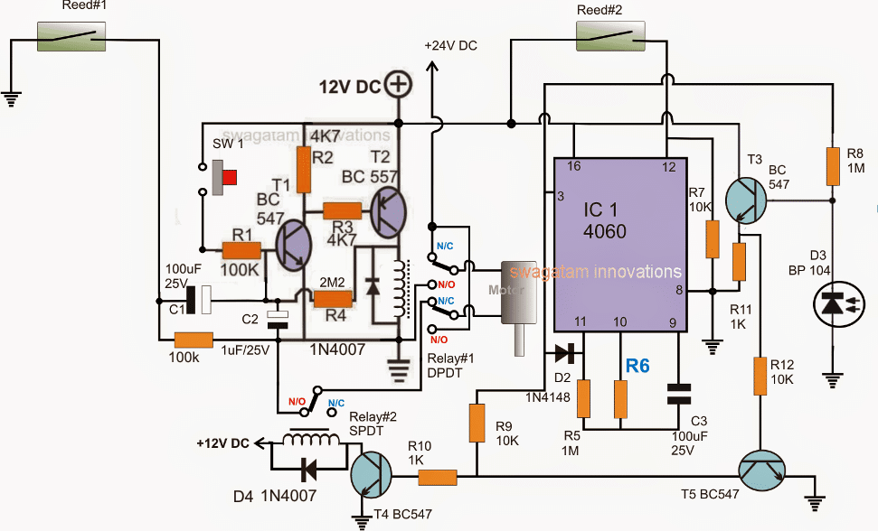
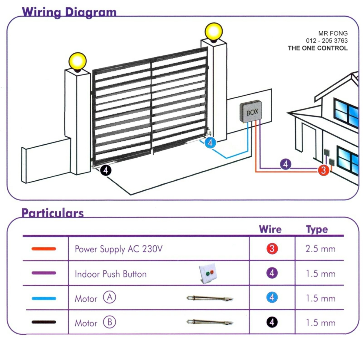
Automatic gate control circuit diagram. Automatic railway gate control system with high speed alerting system is an innovative circuit which automatically controls the operation of railway gates detecting the arrival and departure of trains at the gate. These pins are connected to the servo motor. Connect the pin no 4 and 5 of arduino to l293ds input pins as shown in circuit. The set reset latch using t1t2 the monostable timer using ic 4060 and the ir interceptor using t3t5. Driveway gate information for contractors and consumer education driveway gate and electric gate installation. Swing gate slide gate gate openers operators and telephone entry systems.
The automatic gain control agc amplifiers are another category of amplifiers which can vary its gain according to the input signal levelthey provide enough amplification for the weak signals and prevent strong signals from getting over amplified. The pins d9 and d10 of the arduino are pwm pins. Connect the motor as shown in circuit. Connect the output pins of ir sensors to arduinos pin no 2 and 3 3. Output of all the sensors are connected to a0 a1 a2 and a3 pins of arduino. Various control systems are used to operate automatic gates.
Circuit diagram is shown in pic. Rempart high school previous solution. The proposed automatic sliding gate controller circuit may be understood as explained in the following points. The high current circuit supply a three phases induction motor. Connect all the connection as shown in circuit. Sponsored by gate depotcom.
Connect the ir sensors vcc and gnd pin to arduino 2. Automatic car parking system circuit diagram automatic car parking control circuit diagram standard power supply of 12 volt dc and 5 volt through a regulator are made from a step down transformer along with a bridge rectifier and filter capacitor. The circuit diagram below shows one of these options. Whether youre looking for slide or swing gate openers keypads remotes safety devices control boxes or other operator accessories youve come to the right place. Servos are controlled by sending an electrical pulse of variable width or pulse width modulation pwm through the. Referring to the circuit below it can be divided into three stages.
They were basically designed for the radio receiver circuit which receives highly varying signal strength according to the climatic conditions. Automatic railway gate control circuit diagram. I need a simplified control circuit for an electric gatewhich will open when the open button is pressed and also close whn the close button is pressedthe gate control cicuit diagram shoul contain limit switches to stop the gate in both directions when openning and clossingspring loaded switches should be used as well.
