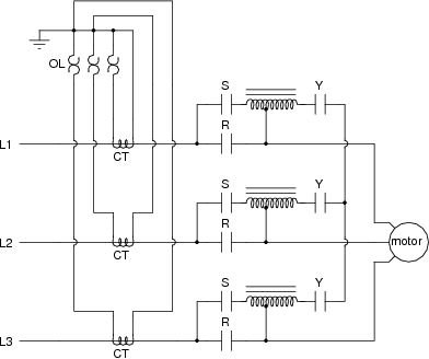
Schematic of an auto transformer starter is shown below. The working of the starter is as under.

New Wiring Diagram Of Auto Transformer Starter Auto
Auto transformer starter control circuit diagram. Readers are encouraged to identify these in. This blog is about electrical concepts and other electrical machines like motor transformerdol starterstar delta starterauto transformer starter. It reveals the components of the circuit as simplified forms and also the power and signal links in between the gadgets. Star delta starter control and power circuit diagram. Explanation of auto transformer with circuit diagram. An auto transformer starter makes it possible to start squirrel cage induction motors with reduced starting current as the voltage across the motor is reduced during starting.
A wiring diagram is a simplified traditional photographic depiction of an electrical circuit. While in auto transformer the primary and the secondary windings are connected magnetically as well as electrically. There are three main contactors that play critical role in auto transformer reduced voltage starting. Auto transformer starter construction and working explained in telugu. Operation of a practical autotransformer starter. In contrast to the star delta connection only three motor leads and terminals are required.
Power circuit and control circuit for a two coil autotransformer starter is shown in figure. Variety of control transformer wiring diagram. Auto transformer starter an auto transformer starter is suitable for both star and delta connected motors. In this method the starting current is limited by using a three phase auto transformer to reduce the initial stator applied voltage. The figure below shows the motor with the auto transformer starter. When the start button is pressed a circuit is completed to the coil of control relay cr causing all cr contacts to close.
Auto transformer starter 10102010 by lemau 9 comments this starter produces high efficiency and have the option to be adjusted to obtain the necessary torque and in accordance with the systemit very efficiency stater but the disadvantage is it very high cost to setup control panel stater. When the coil of s contactor energizes all s contacts change position. In an ordinary transformer the primary and the secondary windings are electrically insulated from each other but connected magnetically as shown in the figure below. Learn about 1159 views. They are the start contactor s main contactor m and the run contactor r.
