When wiring this switch you can choose if youd like to illuminate it because of the independent lamp attached to terminals 8 and 7. Pin 1 is where the rocker switch receives the input power.

Make Your Own Extension Board 13 Steps With Pictures
3 pin switch board wiring. The wiring diagram to the right will show how to wire and power this 12v 20amp on off on 3 way carling contura rocker switch. A wiring diagram is a simplified conventional photographic depiction of an electric circuit. How to wire an led toggle switch on off 3 prong rocker switch 2020 duration. 6 pin toggle switch wiring diagram collection 3 prong toggle switch diagram beautiful rocker switch wiring. Assortment of fender telecaster 3 way switch wiring diagram. 3 position toggle switch wiring diagram elegant switches can a.
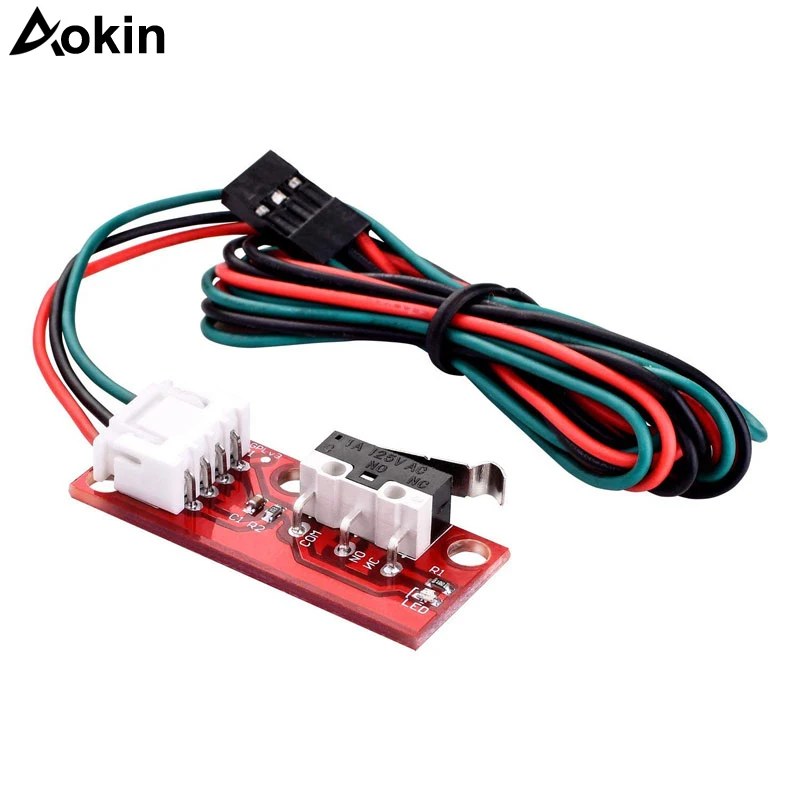
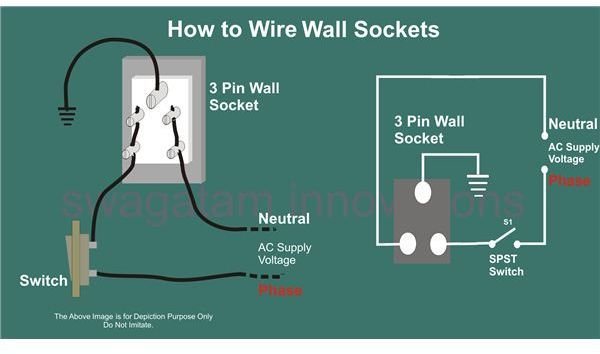
Illuminated on off rocker switch with wiring products duration. The given circuit is a basic switchboard wiring for a light switch and 3 pin socket with control switch. The resistor in that circuit is a pull up resistor required to bias the input high and prevent a short to ground when the switch is closed. The other pole of switch s1 is connected to the lamp. Switched 3 pin socket or how to control a 3 pin socket from a circuit breaker. In this video we show you how to do electric board fitting for 3 sockets and 3.
9 pin toggle switch wiring diagram 6 pin rocker switch wiring. Pin 3 is where the switch is either connected to ground or left open. We have more then 20 years in micro switch on off manufacturingand have got 2 invention patents and 47 utility model patents. Or these terminals can be ignored for non backlit switch banks. How to wire up a switchboard. Wiring products 814104 views.
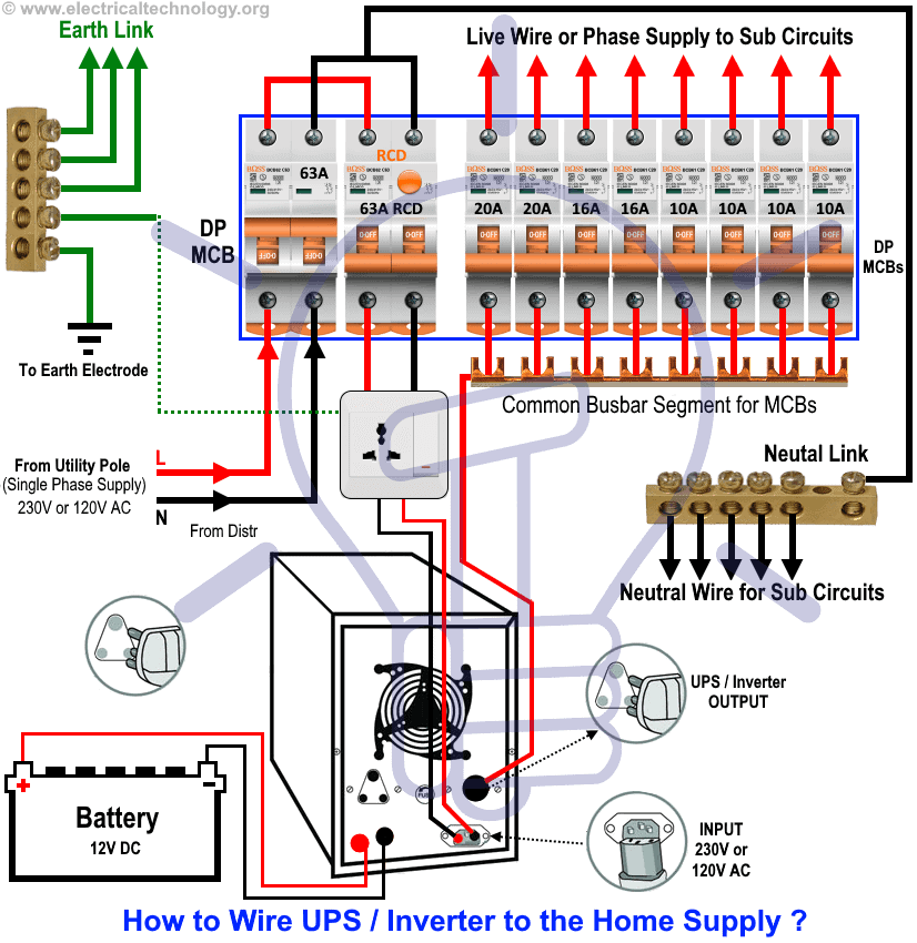
Pin 2 is where the accessory that the switch is going to turn on is connected. This wiring diagram is impotent because by using this wiring connection a person can easily switch off the 3 pin socket or can easily switch on by using the circuit breaker. Switch board wiring connection for tv mobile charger laptopfan lights at your home. It shows the elements of the circuit as streamlined shapes and the power and also signal links in between the devices. When the switch is closed the pin is tied directly to gnd. This translates into the following model in a real life rocker switch.
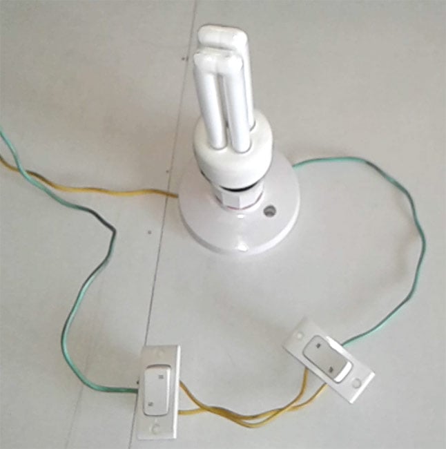
In the below wiring diagram one pole of the both spst single pole single throw switches s1 s2 are connected to the phase line of the supply. Carling toggle switch wiring diagram. When the switch is open the mcu pin is connected through the resistor to 5v. Below is a pictorial representation of the schematic diagram.


