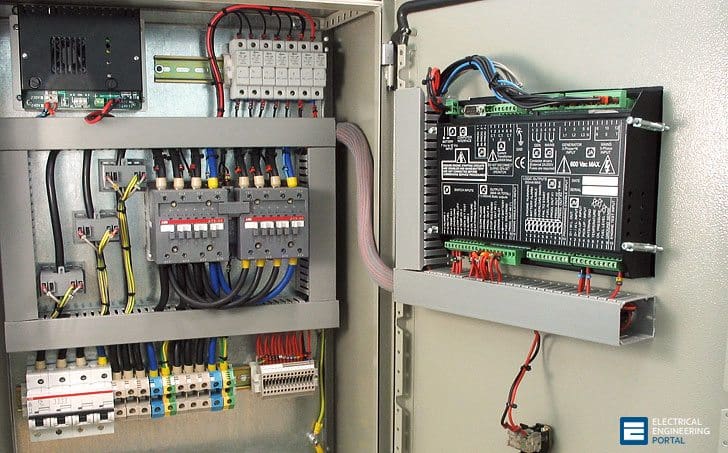
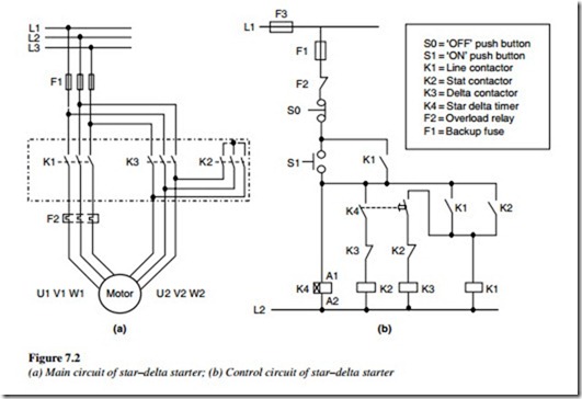
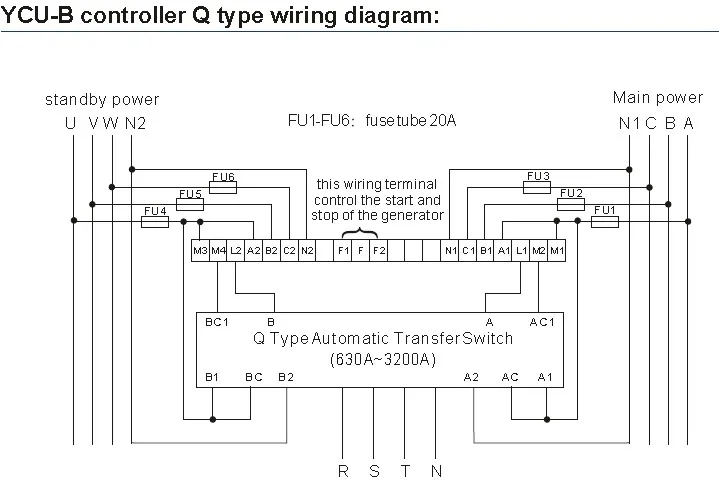
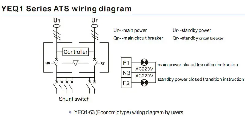
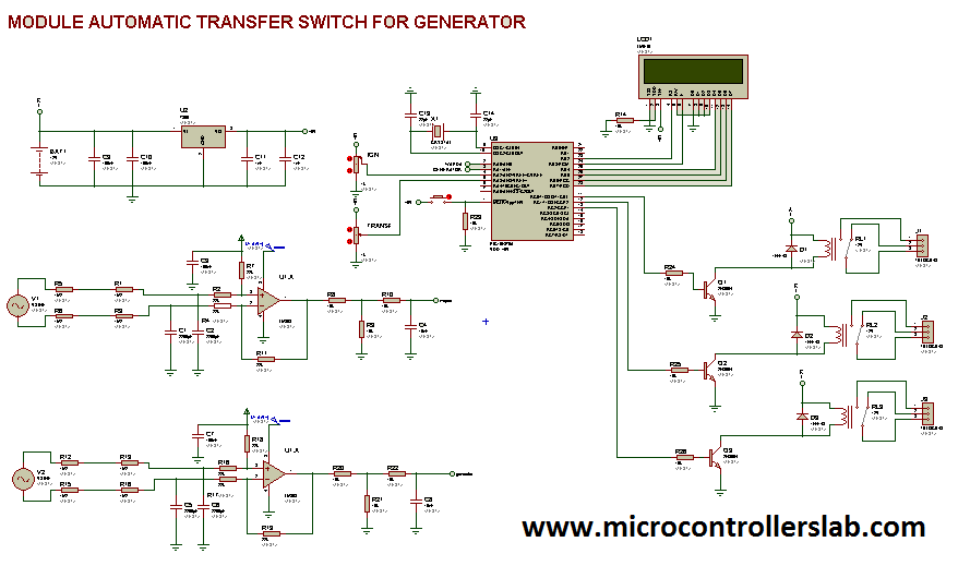
The wires then go to the remote control solder them over the button. A smart way to build an automatic transfer switch is by using two contactors together with an ats controller.

Zhejiang Yuye Electric Co Ltd
Ats panel control circuit diagram. Install a sub panel emdb off of your main panel and use a less. Updated ats circuit diagram with complete ic 4060 and ic 555 wiring details. Diesel generator auto start and stop circuit with diagram and practical in this video we can see you that how to control automatic generator start with these equipment you can use these. Automatic transfer switch circuit diagram. The book describes in simple words and drawings the basic principles to make generator control panels. Ats auto transfer switch power control diagram auto change over power control circuit how to program schneider inverter start up setting of vfd inverter parameter setting bangla.
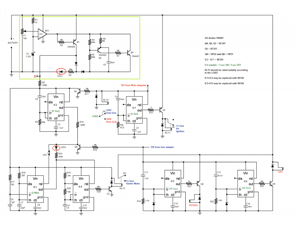
The following article explains an enhanced automatic transfer switch ats circuit which includes several customized sequential changeover relay stages making the system truly smart. Automatic transfer switch diagram. It is about two electrically controlled circuit breakers. The contactors are not allowed to close simultaneously but only one at a time. Learn how to make automatic transfer switch panels. A distribution board also known as panelboard breaker panel or electric panel is a component of an electricity supply system that divides an electrical power feed into subsidiary circuits while providing a protective fuse or circuit breaker for each circuit in a common enclosure.
Ats panel wiring diagram pdf. Motorised switch cl ncl g q1 q2 ats automatic. 15 schematic circuit diagram for automatic transfer switch 16 recommended cable size 17 specifications. The guide includes step by step examples in a way that you will be able to make panels in the size 15 up to 200kva. Superior design and robust construction make jundi electrical industry teco automatic transfer switch the industry. Ats automatic transfer switch panels detect when the mains electricity supply fails and sends a signal to the emergency generator control panel to start the generator.
Manual mode is used for control the ats manually and to start stopping the generator engine. Breaker contactor or motorised switch socomec diagram. Installation constraints inside the enclosure glossary cl ncl g q1 q2 ats transformer cl ncl g q1 q2 ats genset cl ncl g q1 q2 ats critical load cl ncl g q1 q2 ats non critical load cl ncl g q1 q2 ats standard diagram. When the generator control panel senses that the correct voltage and speed measured in frequency expressed as hz the yorpower ats panel switches or transfers the load from. What others are saying ats panel control is the best option in situation wherever you have to control a power generator that is connected to the mains in a standby configuration.

