When there is a power failure on mains 1 the pfr will open. Variety of ats wiring diagram for standby generator.

Ats Control Panel Wiring Diagram Generator Controllers
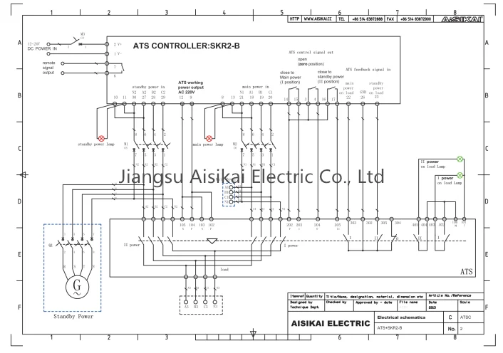
Ats control circuit diagram. The input and output lines to and from the atsgtsups system must have disconnect devices attached. The wires then go to the remote control solder them over the button. During the building power test the auto mode of ats system was not fed to essential power when the city power is. What others are saying ats panel control is the best option in situation wherever you have to control a power generator that is connected to the mains in a standby configuration. Figure 1 atsgts to ups wiring diagram. A wiring diagram is a simplified conventional photographic depiction of an electric circuit.
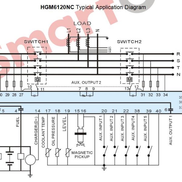
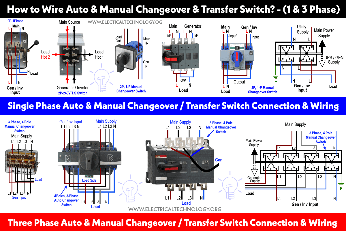
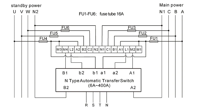
Superior design and robust construction make jundi electrical industry teco automatic transfer switch the industry. If stranded wires are used ferrules or equivalent crimping terminals must be used. The idea of the system is simple. Installation constraints inside the enclosure glossary cl ncl g q1 q2 ats transformer cl ncl g q1 q2 ats genset cl ncl g q1 q2 ats critical load cl ncl g q1 q2 ats non critical load cl ncl g q1 q2 ats standard diagram. Nameplate gives the maximum input current as 25a the circuit breaker should be rated at least 30a. In our step by step electrical wiring installation tutorials series we will show how to wire and connect single phase and three phase automatic and manual changeover and transfer switches to the home distribution board to use the backup power supply such us batteries power with ups and inverters or generator power in case of emergency breakdown and power outage.
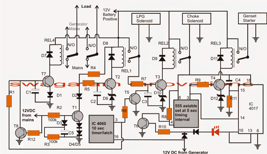
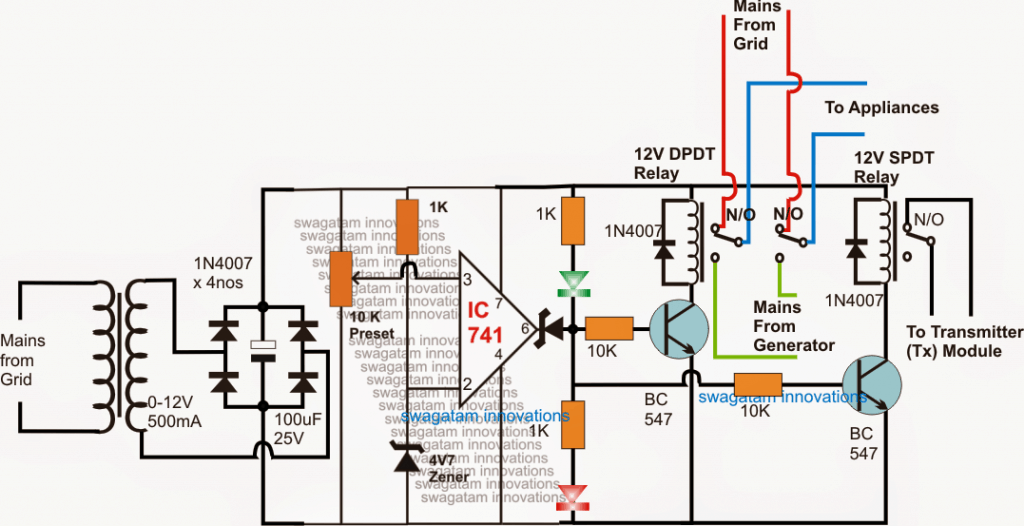
Breaker contactor or motorised switch socomec diagram. The following article explains an enhanced automatic transfer switch ats circuit which includes several customized sequential changeover relay stages making the system truly smart. In this video you will find out how to use phase failure relay in simple auto changeover application. Motorised switch cl ncl g q1 q2 ats automatic. Can you kindly pass me the control circuit diagram for ats. Hi sir i have one client which the lv switchboard include two number of 500a mccb units as the incoming ats for essential and city main power.
Updated ats circuit diagram with complete ic 4060 and ic 555 wiring details. Diesel generator auto start and stop circuit with diagram and practical in this video we can see you that how to control automatic generator start with these equipment you can use these. A distribution board also known as panelboard breaker panel or electric panel is a component of an electricity supply system that divides an electrical power feed into subsidiary circuits while providing a protective fuse or circuit breaker for each circuit in a common enclosure. Ats panel wiring diagram pdf.
Gallery of Ats Control Circuit Diagram