Apfc stands for auto power factor correction panel. In order to improve power factor so that billing is reduced by avoid penalty from governments through introducing kvars into power.

Read Or Download Wiring Diagram Altec 6 04c For Free At
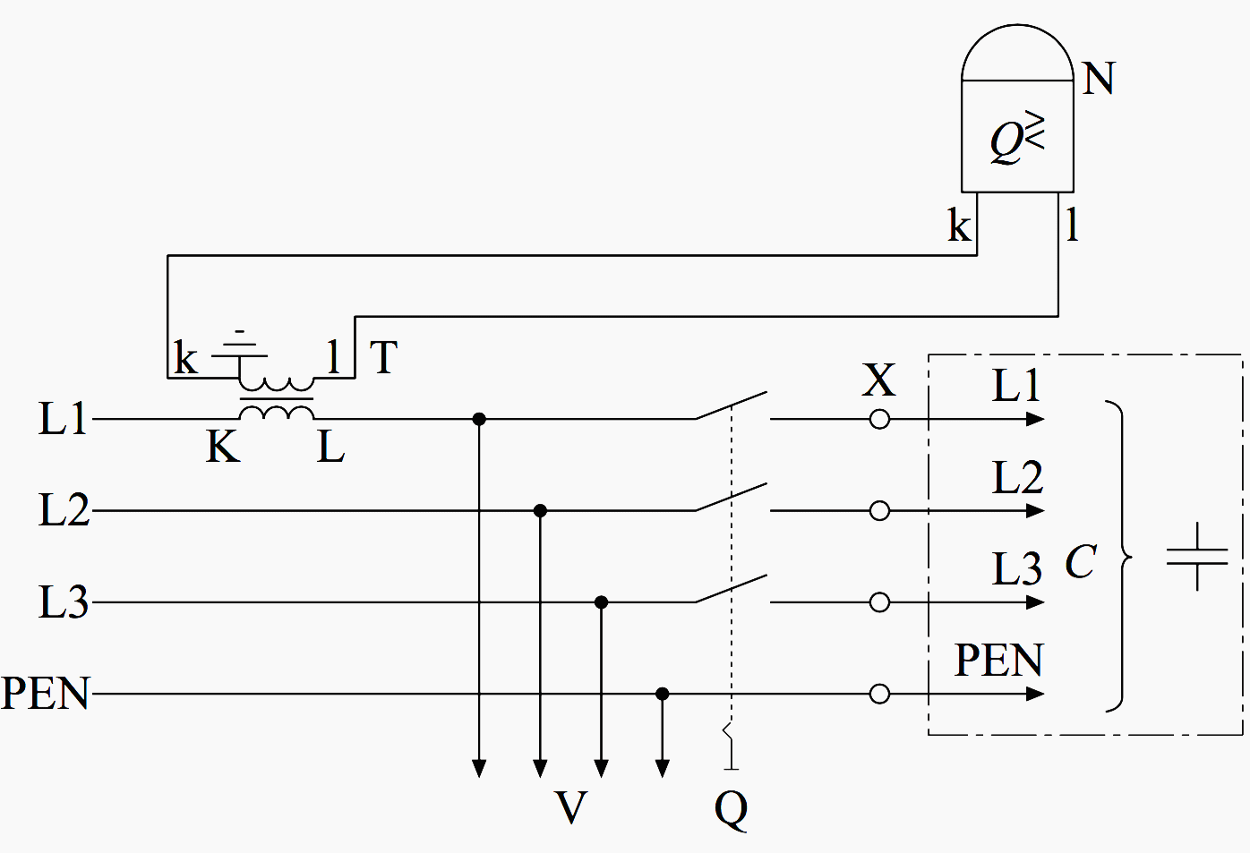
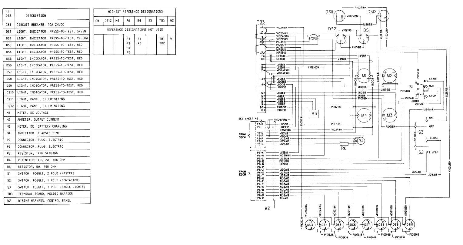
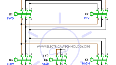
Apfc panel wiring diagram. Design methodology panel design comprising following steps. Control wiring diagram. Refer fig no 3 figm. In case there is no transformer in the installation then the ct for sensing power factor should be provided at the incoming of main switch of the plant. In order to measure electrical power the relay needs to receive the line voltage and current from a current transformer ct installed close to the metering point if possible. Billing can be reduced almost to 40.
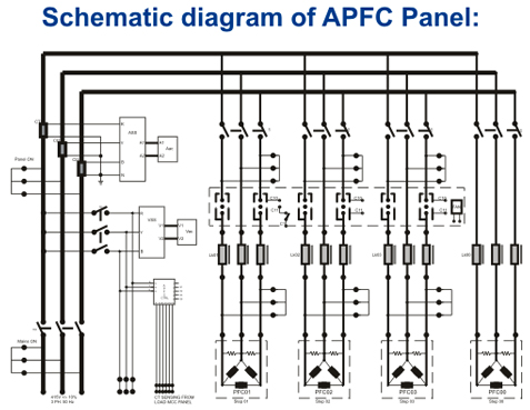
Control panel is complete with all internal wiring and ready for purchasers external cable connections at the outgoing terminals. It is used to improve power factor to meet the current requirement to reduce the billing and also to improve feeder voltage regulation. Figure 1 ga general arrangement figure 1 ga general arrangement figure 2 meter wiring wwwwiring figure 2 meter wiring wwwwiring figure 3 control and power wiring diagram. All wiring inside the control panel is carried out with 1000600 v grade fr lsh. Why we use apfc panel. To measure reactive power at the power factor relay especially it must be ensured that the vectors of voltage and current are shifted by 90.
All inter modular wiring within the control panel for control and interlock looping is carried out by the control panel supplier. Note that apfc panel can maintain the power factor on lt side of transformer and it is necessary to provide fix compensation for power transformer refer fig no 1 5. Basic theory of apfc panel. Circuit diagram of pf relay.
