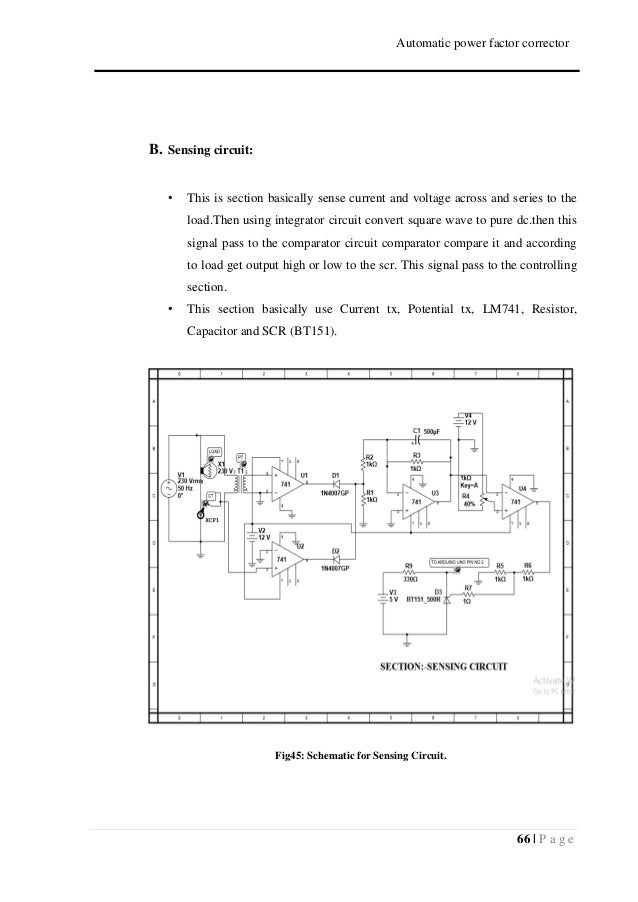
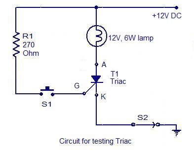
During the positive half cycle of the sinusoidal waveform the device is forward biased but with switch s 1 open zero gate current is applied to the thyristor and it remains. The apfc panel builders can use tsc 307 cards as an independent firing card and can wire the scr modules separately mounted on the heat sink in the panel.

Electrical Control Panels Royal Power Control
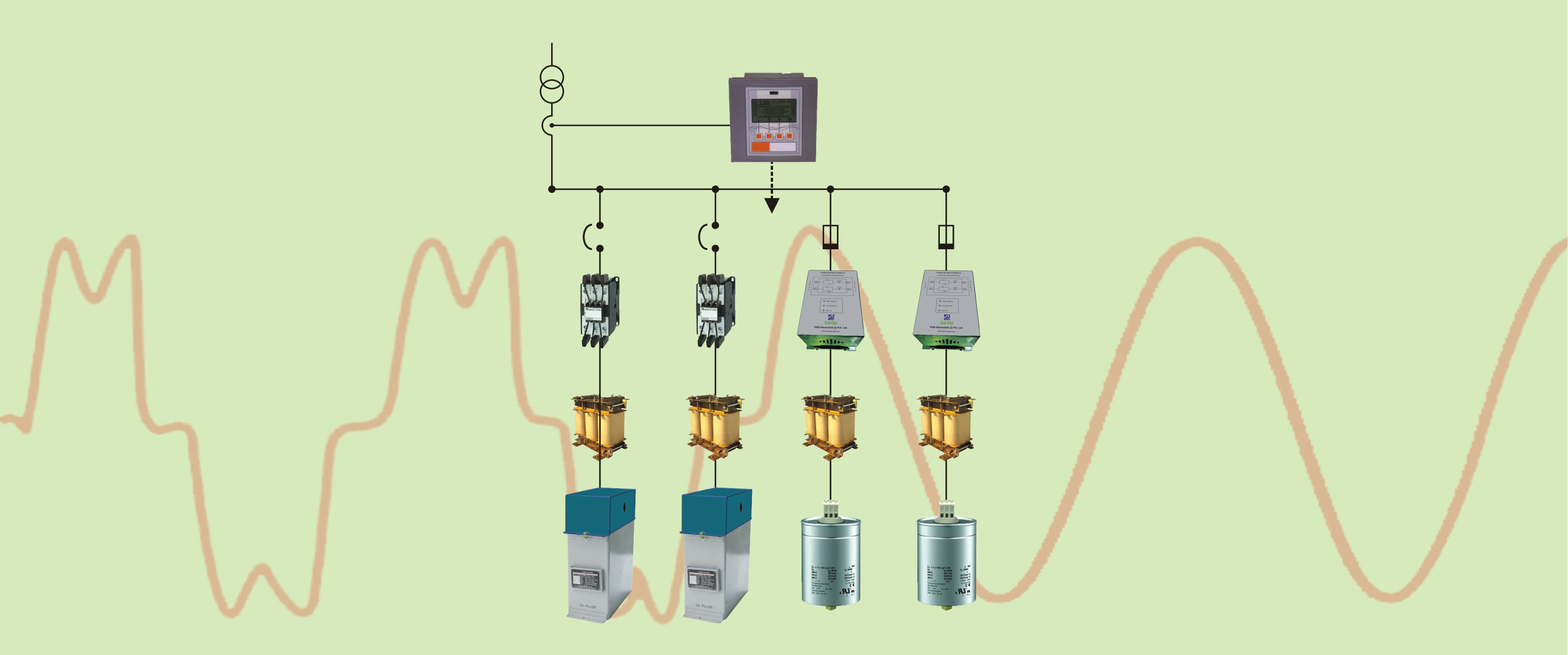
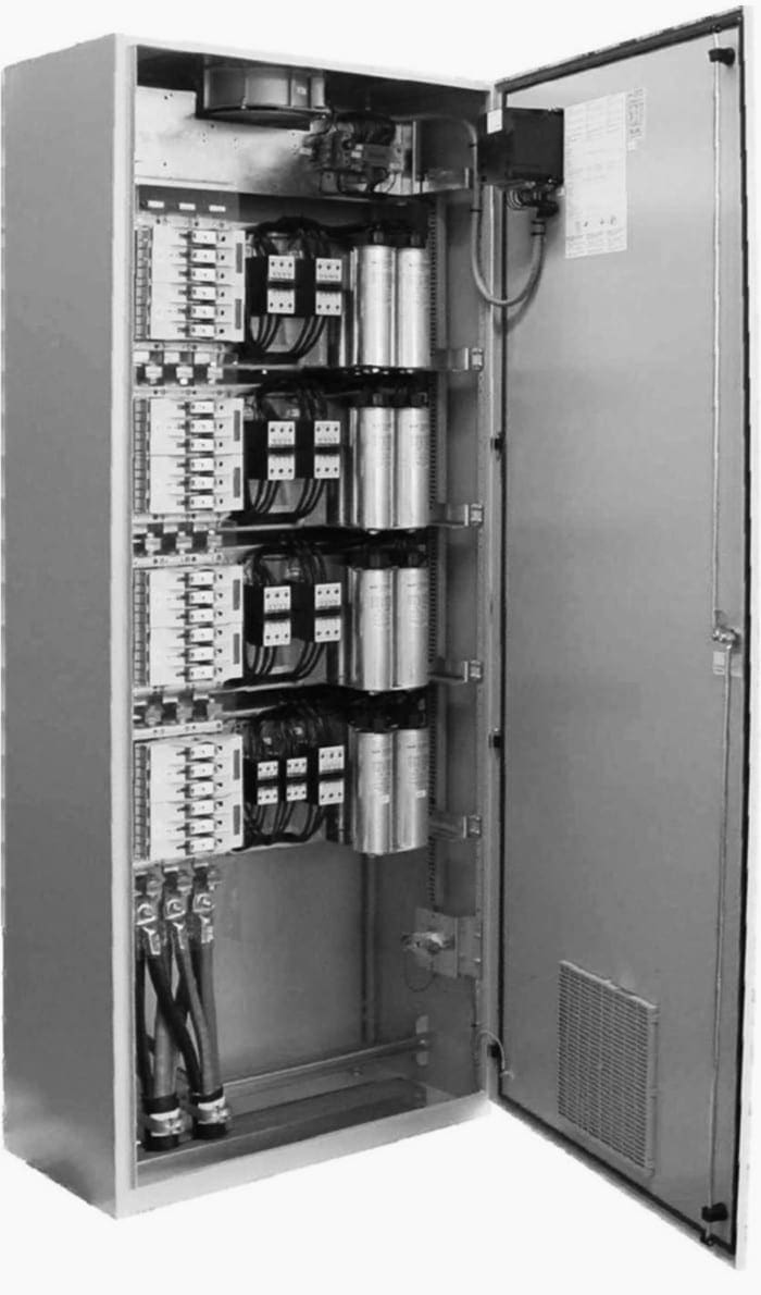
Thyristor based apfc panel wiring diagram. Hence for each output from apfc it will be required to use 6 to 12 nos. This control circuit will control the load power factor by sensing various parameters like switching devise thyristor inductors capacitor banks etc. It consist of high grade thyristor with fuses mcbs and mccbs heaters contactors isolation switches indication lamps alarm system etc. The apfc panel has a number of capacitor banks and busbars that carry large currents. Thyristor control panels are basically used to control voltage and monitor the working of heaters and variable applications in a production line. Apfc is an automatic power factor control panel which is used to improve the power factor whenever required by switching on and off the required capacitor bank units automatically.
All wiring inside the control panel is carried out with 1000600 v grade fr lsh. Apfc electrical thyristor apfc panel control wiring diagram apfc panel control wiring diagram in hindi apfc panel working in hindi apfc panel testing thyristor based apfc panel wiring. It consists of a power capacitor connected in series with a bidirectional thyristor valve and usually a current limiting reactor the thyristor switched capacitor is an important component of a static var compensator svc where it is often used in conjunction with. It is used to improve power factor to meet the current requirement to reduce the billing and also to improve feeder voltage regulation. The physical isolation of electronic. All inter modular wiring within the control panel for control and interlock looping is carried out by the control panel supplier.
21 circuit diagram of 3 ø system figure 4. Auxiliary power supply. The apfc panel will have an auxiliary power supply that powers its various functional blocks. Apfc stands for auto power factor correction panel. Voltage across the thyristor is zero. The above thyristor firing circuit is similar in design to the dc scr circuit except for the omission of an additional off switch and the inclusion of diode d 1 which prevents reverse bias being applied to the gate.
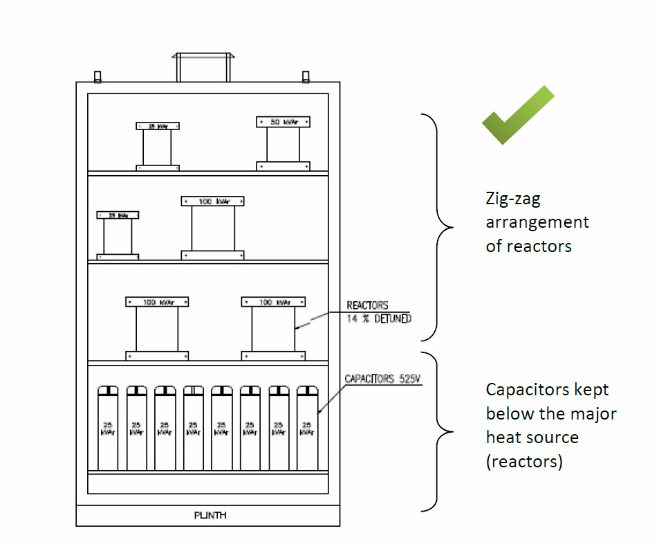
Control panel is complete with all internal wiring and ready for purchasers external cable connections at the outgoing terminals. We manufacture a wide range of these panels. Power factor is the ratio of active power to apparent power and it is a major component in measuring electrical consumption. A thyristor switched capacitor tsc is a type of equipment used for compensating reactive power in electrical power systems. Block diagram of 3 ø system this figure 4 seems that power circuit diagram of rtpfc panel. Exhaust fans are used to maintain the temperature of the apfc panel.
