In the sections below you will find exploded diagrams of some of the most popular compressor parts and how they may vary depending on the manufacturer. Safety when wiring a compressor pressure switch.

Dual Air Brake Georgia Commercial Drivers Manual 2019
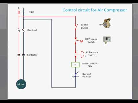
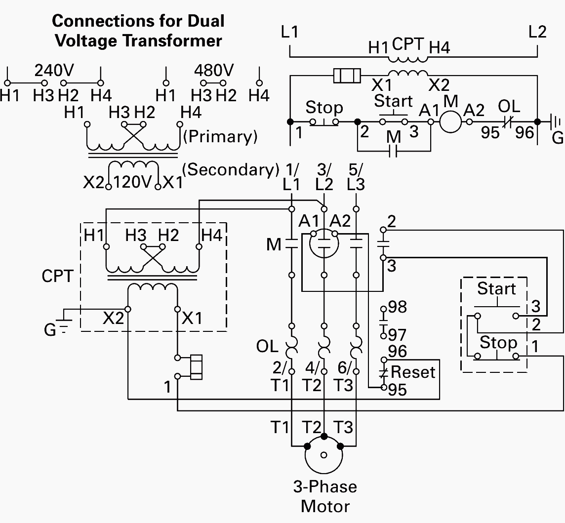
Air compressor control circuit diagram. Control circuit for air compressor bmanishap. Variety of air compressor pressure switch wiring diagram. Ladder diagram basics 3 2 wire 3 wire motor control circuit duration. When changing the voltage of the motor be sure to see the wiring diagram on the motor label and make sure of the circuit voltage which is supplied to the. There you will see the wiring diagrams for motor control relays. It reveals the parts of the circuit as simplified forms as well as the power and also signal connections between the tools.
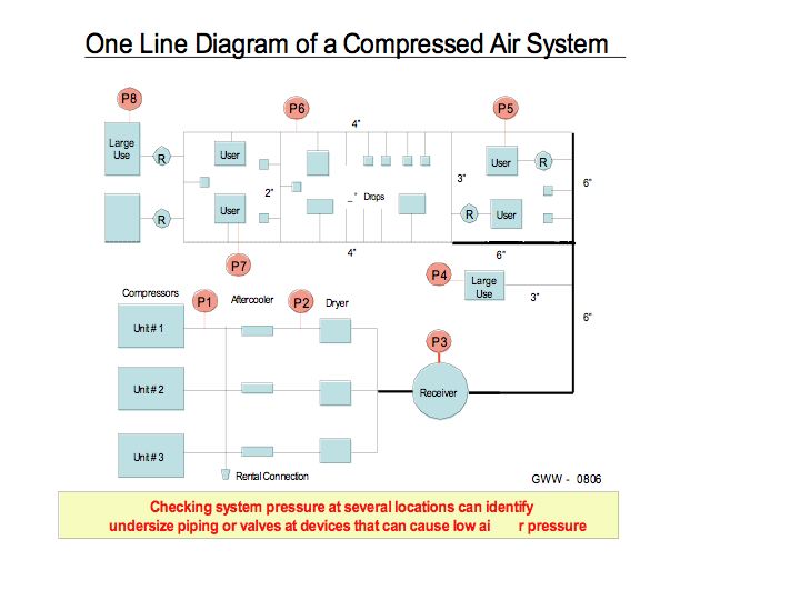
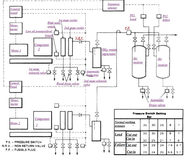
If you are working on a switch with 240 vac the power there will kill you if you are not very careful. In three ph ases. Firstly compressor startup without load. Wiring a 3 phase motor for an air compressor the basic requirements for wiring electric motors 3 phase motor circuits. In operation a pressure switch turns the power on and off to an air compressor motor. Air compressor system schematic diagram.
Piston air compressors a piston compressor also known as a reciprocating compressor uses pistons driven by a crankshaft to deliver air at high pressure. If you are well grounded the power in a 120 vac circuit can kill you. When the air compressor is plugged in. Control features of a air compressor system is categorized. A wiring diagram is a simplified traditional pictorial depiction of an electric circuit.
Gallery of Air Compressor Control Circuit Diagram