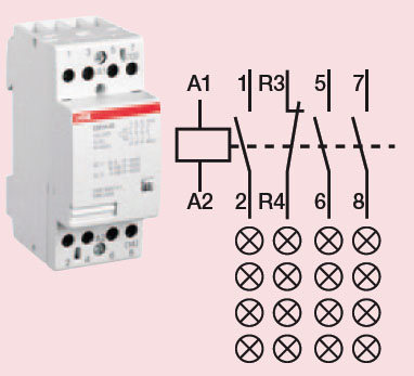
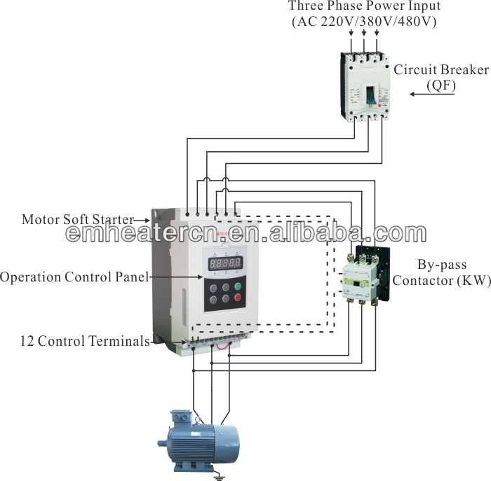
A wiring diagram is a simplified standard pictorial representation of an electric circuit. Abb industries and utilities.

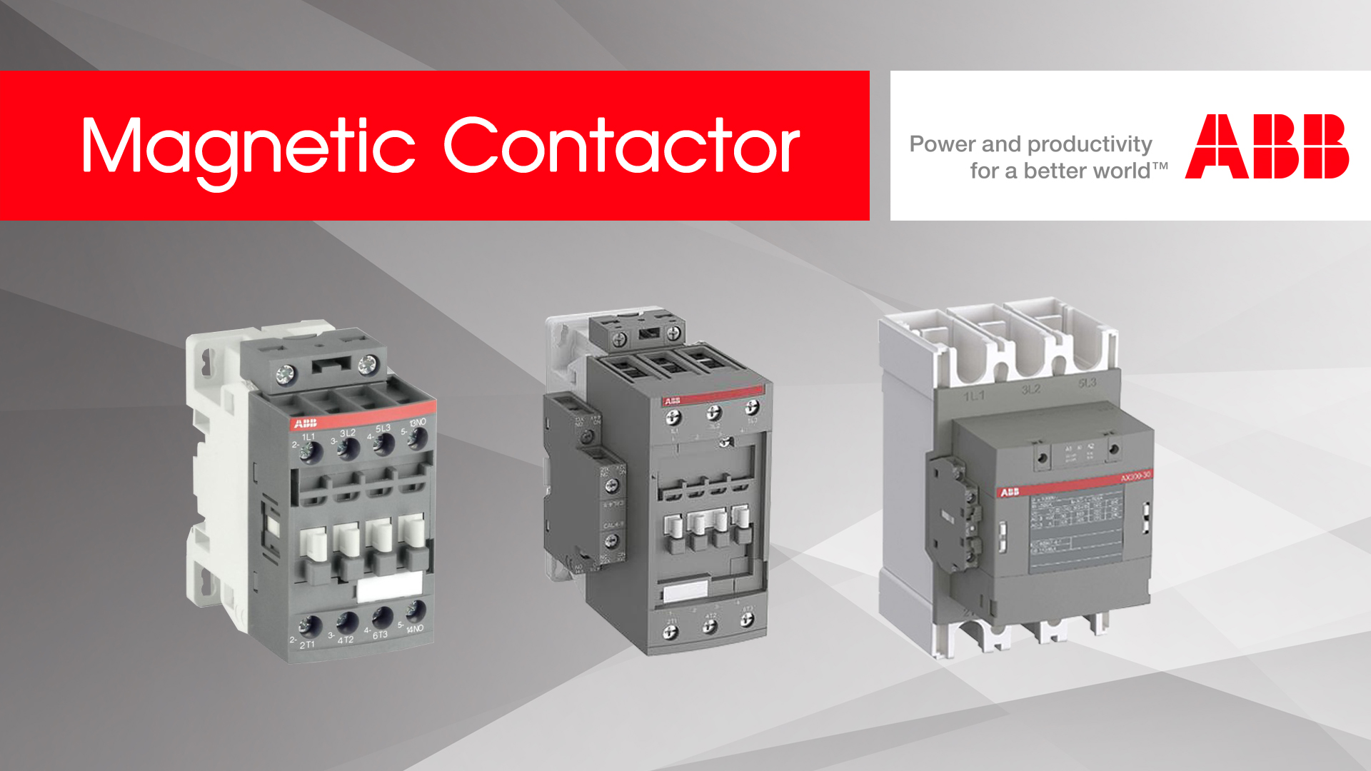
4 Pole Contactors For Power Switching Motor Protection And
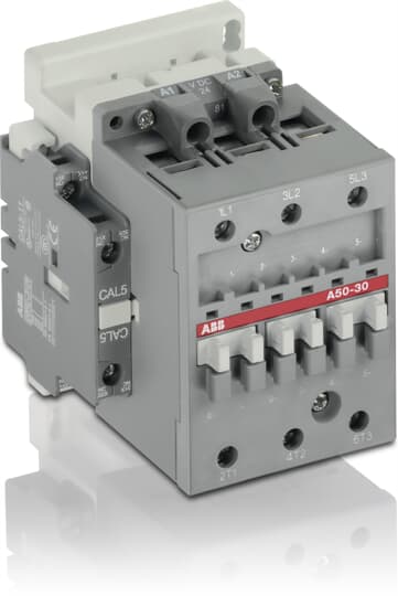
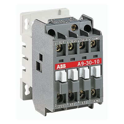
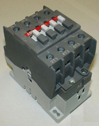
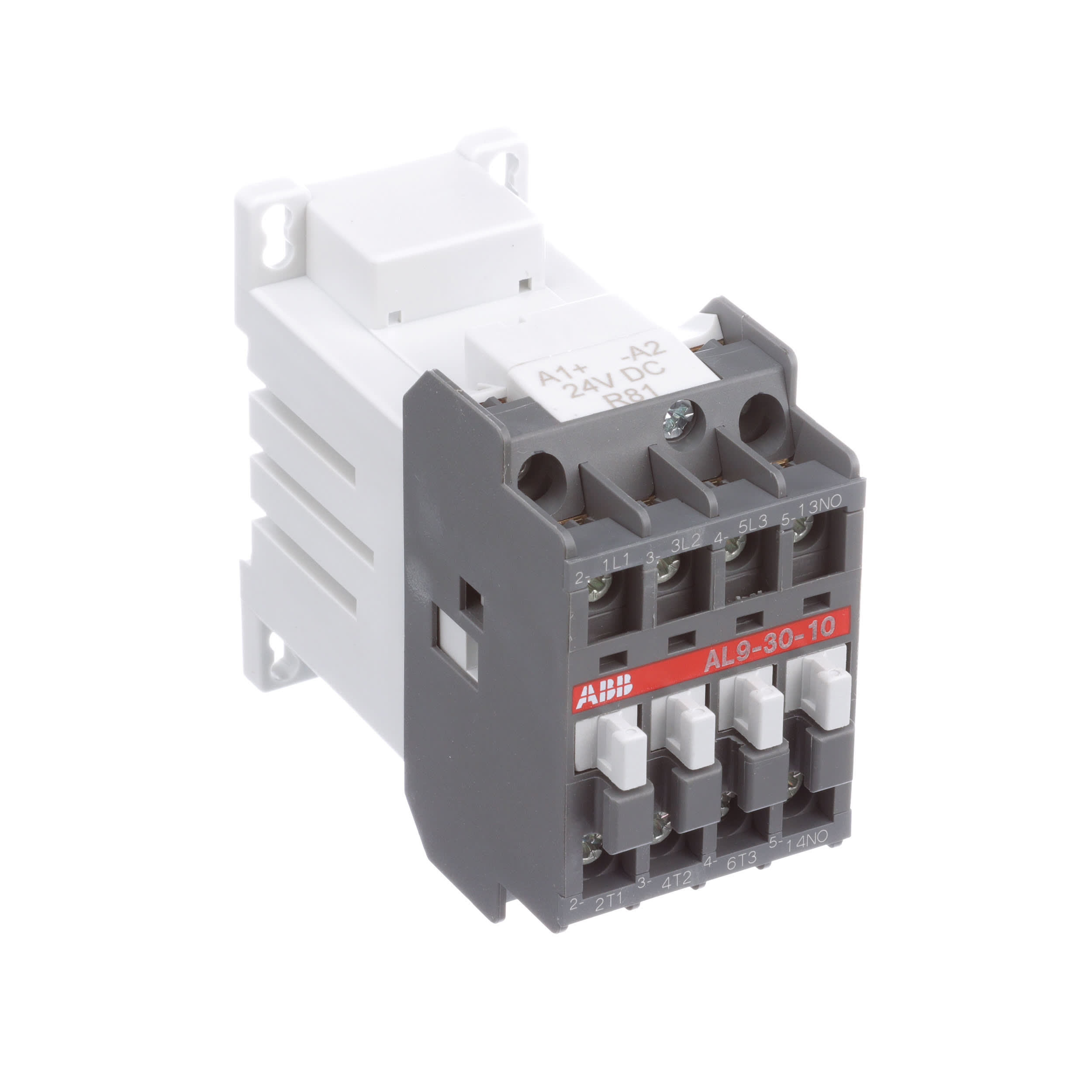
Abb contactor wiring diagram. Many large pieces of equipment are powered directly from high voltage lines. They are ideally suited for applications where reliability is a must and space is at a premium. The v lmt contactor carriage is fully interchangeable with lmt lms lmr lsr lmvp hd4 lmt and vd4 lmt circuit breakers providing a high degree of flexibility in. Assortment of abb a16 30 10 wiring diagram. Abb 3 pole contactors offer an exhaustive selection of products for simple and extreme applications as well as products with specific purposesthe af contactor technology revolutionizes how we use contactors and allows use in all parts of the world and in all network conditions. 3 pole contactors and overload relays for motor starting and power switching.
240 volts ac and 480 volts ac are commonly used for these large pieces of. Abb offers a wide variety of discrete medium voltage apparatus to serve oems and to fulfill repair retrofit and upgrade needs. Do not make any voltage tolerance tests hi pot or megger on any part of the unit. Contactor type c non reversing defi nite purpose frame size 20 20a 25 25a 30 30a 40 40a 50 50a 60 60a. Abb 2117 32e avenue lachine qc h8t 3j1 tel. Installing the wiring supplement to ach550 uh users manual warning.
Variety of 2 pole contactor wiring diagram. How to wire a contactor. These lines far exceed the 120 volts ac standard in most homes. To make the most you need control. Abb library is a web tool for searching for documents related to abb products and services. It reveals the components of the circuit as simplified shapes as well as the power and signal connections between the gadgets.
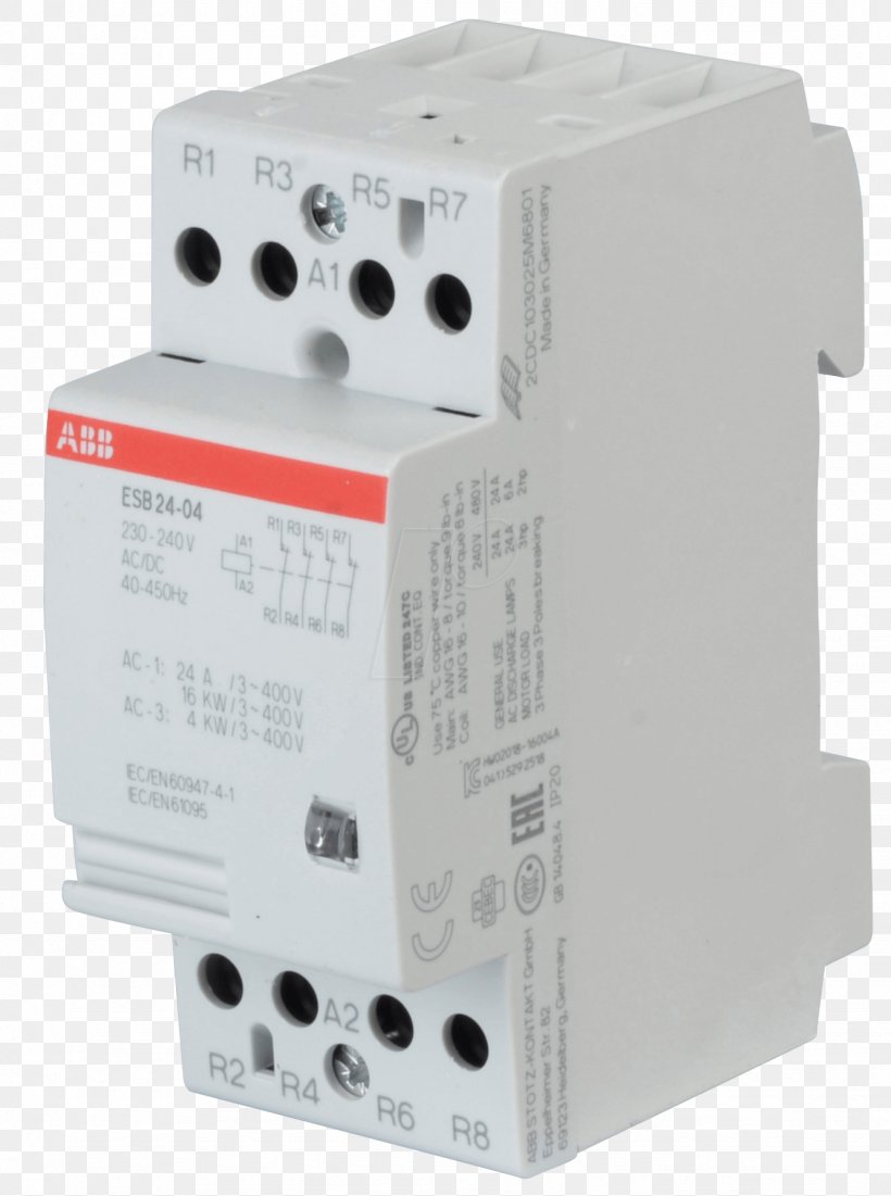
1 see diagram on page 7 for approximate dimensions and description. Key products include contactors circuit breakers current limiters railway traction equipment enclosures switch disconnectors fuses apparatus for outdoor applications voltage indicators and connectors relays instrument transformers and sensors all. Vb6 30 01 01 mini revcontactor 24v 40 450hz. Never connect line voltage to drive output terminals t1 t2 and t3. Do not connect or disconnect input or output power wiring or control wires when power is applied. It reveals the components of the circuit as streamlined forms and the power and signal links in between the tools.
A wiring diagram is a simplified traditional photographic depiction of an electrical circuit. The vb6 30 01 mini reversing contactor is a compact 3 pole contactor with 1 auxiliary contact screw terminals and normal mechanical interlock.
Gallery of Abb Contactor Wiring Diagram