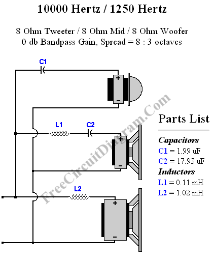
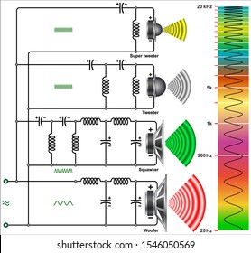
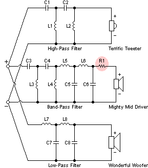
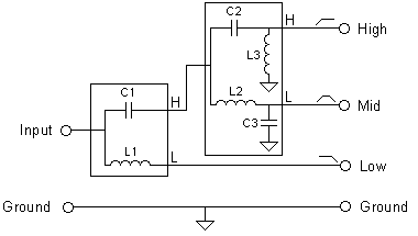
C1199 uf c21793 uf l1011 mh l2102 mh. 07052019 3 way crossover network circuit diagram dividing network diagram 3 way speaker crossovers circuit diagram image dividing network diagram high pass crossover example dividing network diagram 10 is a schematic diagram of an electrical circuit or crossover network for a loudspeaker the crossover network divides the.
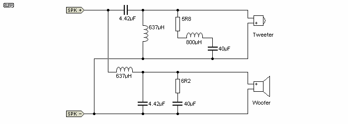
Passive Crossover Network Design
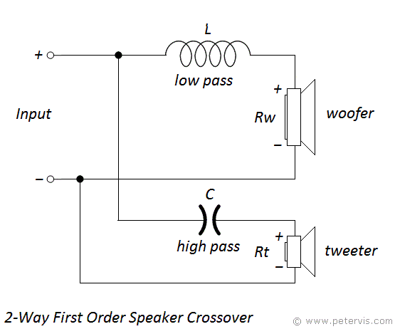
3 way crossover network circuit diagram. Each part ought to be placed and linked to different parts in specific manner. The input audio signals that enter the circuit are filtered by the inductor and capacitor network. You should also review the crossover guide for help with this example. This is a conventional 12db octave unit and cannot be expected to have the same performance as a linkwitz riley aligned. Designing a crossover network for two way speakers system. The speaker crossover network we will build to divert low frequency sounds to a woofer and high frequency sounds to a tweeter is shown below.
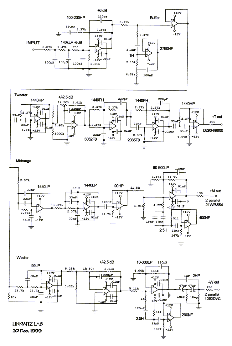
If not the arrangement wont work as it should be. For this example i picked 3 scanspeak drivers for a 3 way speaker the same 3 used on the speaker box examplenote. Small 3 way stereo speaker build. For 2 way speaker system in case of the first order filter you just need a capacitor and inductor. The result is better achieved using a circuit network of inductors and capacitors also called the crossover network. 3 way active crossover this is diagram about 3 way active crossover.
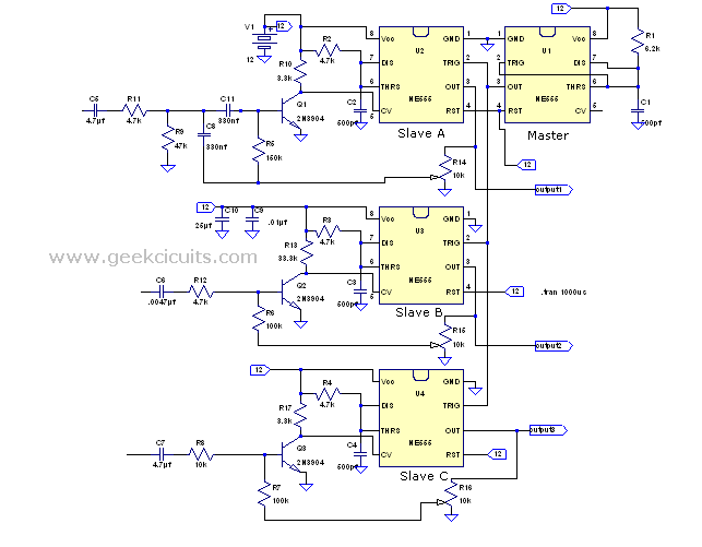
Speaker crossover network circuit. More info on reading a crossover diagram. A simple 3 way crossover intended for triamping hi fi systems. Speaker crossover wiring diagram 3 way speaker crossover wiring diagram car speaker crossover wiring diagram component speaker crossover wiring diagram every electrical arrangement is composed of various unique pieces. 1st order 3 way crossover circuit diagram the parts list. The first order crossover network is the simplest need only a capacitor for the high pass and and an inductor for the low pass.
3 way crossover design example note this sample crossover makes use of many of the calculators found on the menu on the left. This example old and the characteristics of these drivers have since changed. Lets say you have a 8 ohm woover and a 8 ohm tweeter. The circuit operates on the principle of filtering systems. Get a vivid information regarding 3 way speaker crossovers and learn how these networks in a three way speaker system can produce a hi fi quality output due to proper separation of music frequencies through them. Speaker crossover hand wound inductor coil made from trash extremely temporary prototype.
Design a 3 way all pass crossover for your next speaker project.

