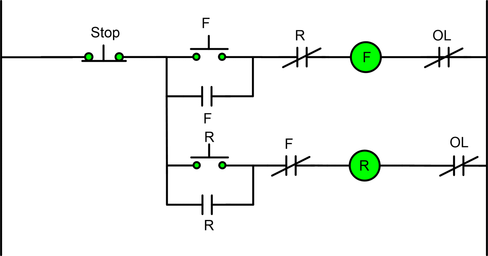
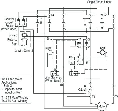
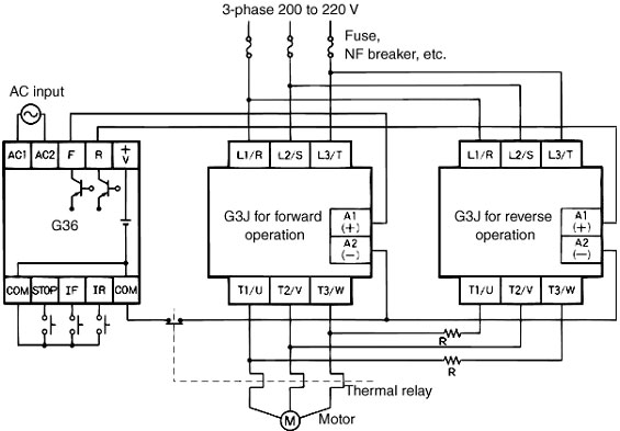
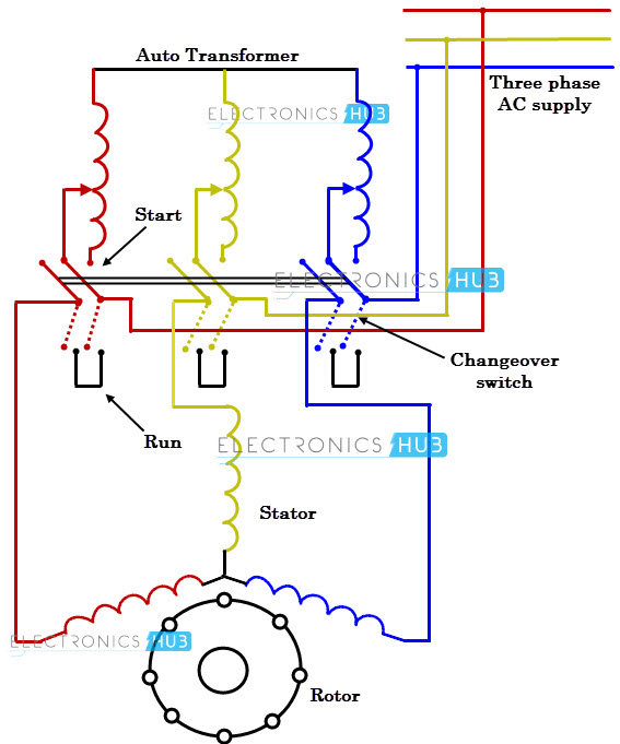
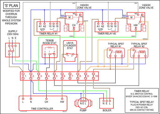
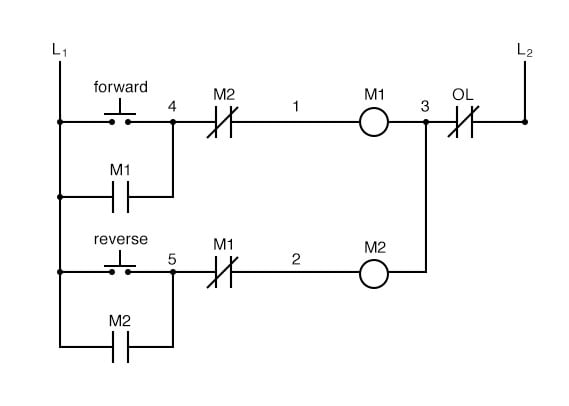
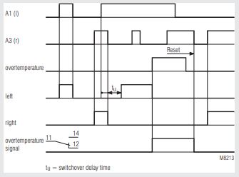
The usual aspects in a wiring diagram are ground power supply cord and link outcome devices switches resistors reasoning entrance lights etc. In the 3 phase motor forward reverse starter wiring diagram.
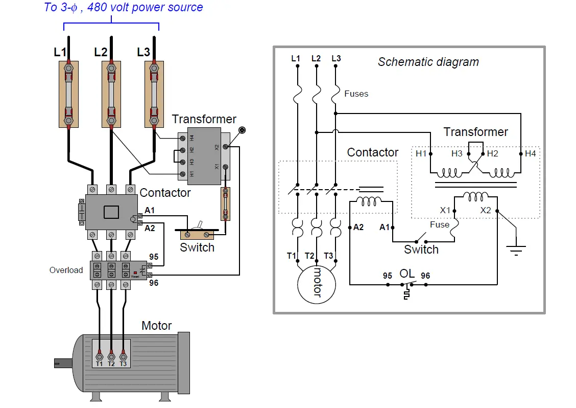
Motor Control Circuit Wiring Instrumentation Tools
3 phase reversing contactor wiring diagram. Wiring diagram book a1 15 b1 b2 16 18 b3 a2 b1 b3 15 supply voltage 16 18 l m h 2 levels b2 l1 f u 1 460 v f u 2 l2 l3 gnd h1 h3 h2 h4 f u 3 x1a f u 4 f u 5 x2a r power on optional x1 x2115 v 230 v h1 h3 h2 h4 optional connection electrostatically shielded transformer f u 6 off. How to do contactor wiring for 3 phase induction motor with 3 pole circuit breaker overload relay nonc push button switches in this tutorial post i will tell you about motor contactor wiring and its diagram. 2 phase and 3 phase. In the above one phase motor wiring i first connect a 2 pole circuit breaker and after that i connect the supply to motor starter and then i do cont actor coil wiring with normally close push button switch and normally open push button switch and in last i do connection between capacitor. To read a wiring diagram first you need to know exactly what basic components are included in a wiring diagram and also which pictorial icons are used to represent them. I shown the 3 pole mccb circuit breaker 2 magnetic contactor normally open normally close push button switch thermal overload relay 3 phase 4 wire system supply 3 phase motor with connection trip indicator light etc.
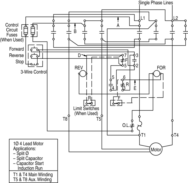
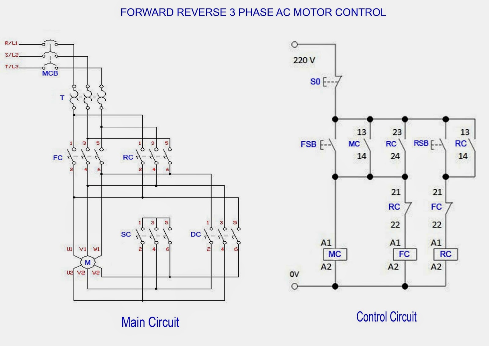
The following diagram depicts 3 phase non reversing motor control with 24 vdc control voltage and manual operation. The above diagram is a complete method of single phase motor wiring with circuit breaker and contactor. In the video i explained the two 3 phase motor forward reverse starter wiring diagram. This video is about the 3 phase motor reverse forward motor control circuit diagram. Here are a few of the leading drawings we obtain from various sources we wish these pictures will serve to you and with any luck very appropriate to just what you want about the reversing motor starter wiring diagram is. 800 x 600 px source.
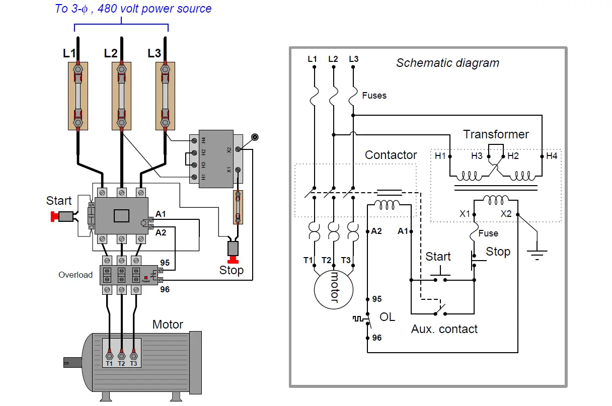
Single phase reversing contactor wiring diagram. Single phase forward reverse motor wiring diagram concerbiz size. A wiring diagram is a simplified conventional pictorial representation of an electric circuit. We will use a contactor an auxiliary contact block an overload relay a normally open start pushbutton a normally closed stop pushbutton and a power supply with a fuse. Output of these contactor is fed to the motor through overload relay for the protection of the motor. Reversing dc starters constant and.
Full voltage non reversing 3 phase motors. Here connect the 3 phase supply to the over load relay same as input to run the motor in forward direction but in case of the reverse contactor we have to reverse one phase for the reversing of direction of motor as shown in the diagram. Why 3 phase ac instead of single phase. In the above one phase motor wiring i first connect a 2 pole circuit breaker and after that i connect the supply to motor starter and then i do cont actor coil wiring with normally close push button switch and normally open push button switch and in last i do connection between capacitor. How to wire a contactor and.


