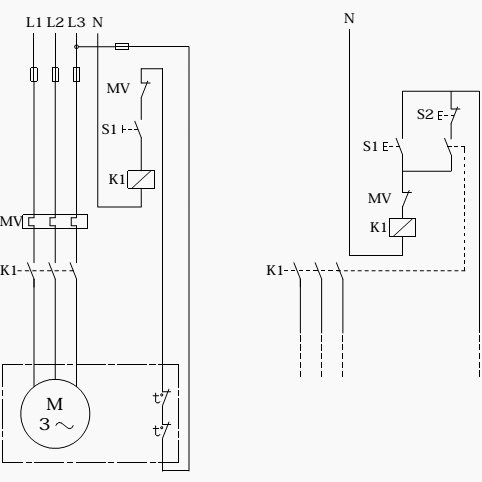
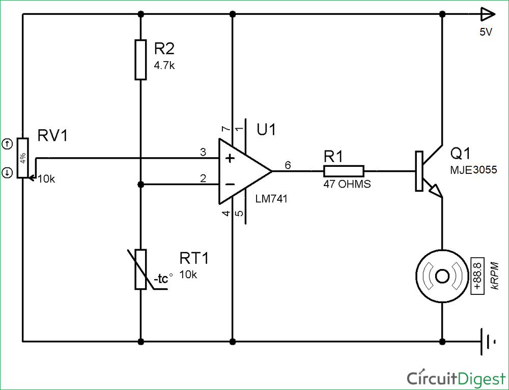
Capacitor motor single phase wiring diagrams always use wiring diagram supplied on motor nameplate. The resistance in the sensor remains relatively low and constant over a wide temperature band and increases abruptly at a pre determined temperature or trip point.

Industrial Motor Control The Motor And Starting Methods
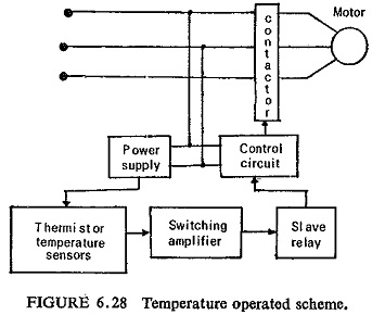
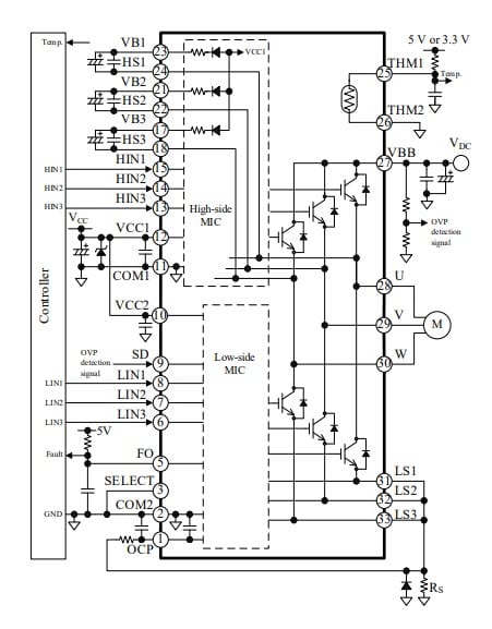
3 phase motor thermistor wiring diagram. Two phase motor wiring diagram wiring diagram is a simplified customary pictorial representation of an electrical circuitit shows the components of the circuit as simplified shapes and the capacity and signal contacts between the devices. The thermistor has to be connected to a control circuit which can convert the resistance signal which again has to disconnect the motor. Thermistor protection relay tpr is designed for mounting inside a control cubicle or motor control center mcc usually on standard terminal rail. Three phase electrical wiring installation in home iec nec. Used in three phase motors. You may also read.
W2 cj2 ui vi wi w2 cj2 ui vi wi a cow voltage y high voltage z t4 til t12 10 til t4 t5 ali l2 t12 ti blu t2 wht t3org t4 yel t5 blk t6 gry t7 pnk. A three phase motor has two main parts. The rotor which turns and the stator that turns it. One line diagram of simple contactor circuit. For alarm and trip control of a 3 phase ac induction motor. The stator consists of a ring with three pairs of coils evenly spaced around the rotor.
The figure 6 shows a typical connection of two thermistor protection relays and their associated groups of thermistor sensors. The rotor is often called a squirrel cage because it consists of a circular network of bars and rings that look a bit like a cage connected to an axle. Multi speed 3 phase motor 3 speeds 1 direction power control diagrams. How to connect a portable generator to home supply system three methods a simple circuit diagram of contactor with three phase motor.

