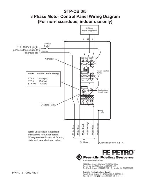
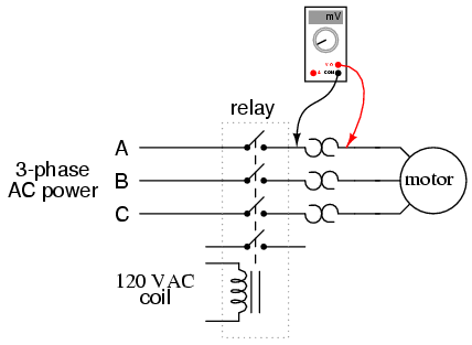
On abb contactor wiring diagram. Here i showed the forward reverse wiring diagram.

3 Phase Motor Wiring Diagram And Symbols Redbulluiq 7
3 phase motor control wiring diagram. In the diagram i connect the incoming three phase supply l1 l2 l3 to the mccb circuit breaker molded case circuit breaker. Figure 1 is a typical wiring diagram for a three phase magnetic motor starter. They can be used as a guide when wiring the controller. Three phase electrical wiring installation in home iec nec. If the volt ages are different it is called separate control. 28 images residential electrical wiring diagrams wiring diagram schematic diagram of electric motor wiring diagram and 25 best ideas about electrical wiring diagram on 25 best ideas about.
Please explain to me if i must really put a contactor on my 3 phase motor. I had to do this a few times with floodlights to be used outside. In the above three phase dol starter wiring diagram. 33 l1 l2 l3 n suggested wiring arrangement selector switch hi speed contactor overload overload lo speed contactor these diagrams are current at the time of publication check the wiring diagram supplied with the motor. Starting a three phase motor. 3 phase dol starter control and power wiring diagram.
Please explain to me. This video gives a brief explanation on how a three phase motor control circuit works. Wiring diagram parts list design worksheet duration. Refer to the motor manufacturers data on the motor for wiring diagrams on standard frame ex e ex d etc. How does a 3 phase induction motor start. All connection i shown with complete guide.
Figure 1 typical wiring diagram. Water pump controller with float switch duration. In the below dol starter wiring diagram i shown a molded case circuit breaker a magnetic contactor normally open push button normally close push button switch thermal overload relay motor trip indicator and 3 phase motor. Start stop 3 wire control. 2 contactors burned out in one day but nothing wrong with motor. Multi speed 3 phase motor 3 speeds 1 direction power control diagrams one line diagram of simple contactor circuit.
They show the relative location of the components. We use 2 magnetic contactors as forward reverse switch. The control circuit is separate from the motor circuit. Typical starter wiring diagram three phase. Forward reverse motor control diagram for three phase motor for three phase motor forward reverse control circuit. Motor is a hi low 3 phase motor on a air compressor.
Ryb electrical 86679 views. Basic wiring for motor control technical data. And can i not just run it straight without a contactor. The control circuit may not be at the same voltage as the power circuit. When the voltage of the control and power circuits is the same it is referred to as common control.


