Click here to view a capacitor start motor circuit diagram for starting a single phase motor. 240 volt single phase wiring diagram 220 volt single phase motor wiring diagram 220 volt single phase wiring diagram 240 volt single phase motor wiring diagram every electric arrangement is composed of various unique components.

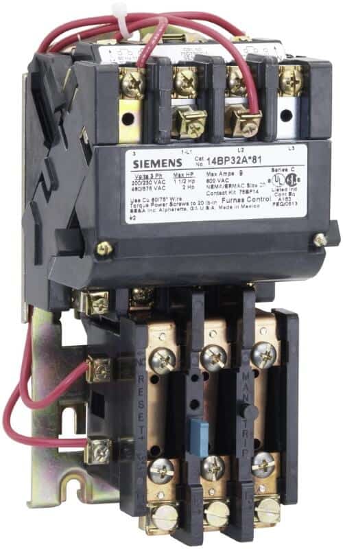
Magnetic Electric Motor Starter Control 5 Hp Single Phase 220
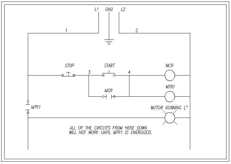
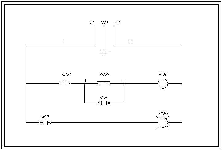
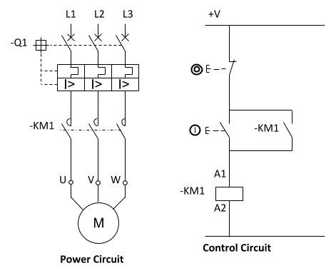
240v motor starter wiring diagram. Look at the underside of the cover for the wiring diagram which specifies which wires are used to wire the motor for 240 volts. Variety of 240v motor wiring diagram single phase. Ic1 2 ocdeecvglgl. Diagram ic2 m 1 240v ac 0 10v outp ut diagram ic3 m 1 0 10v 4 20ma 240v ac outp uts these diagrams are current at the time of publication check the wiring diagram supplied with the motor. In north america an induction motor will typically operate at 230v or 460v 3 phase 60 hz and has a control voltage of 115 vac or 24 vdc. The below wiring diagram shows how we would assemble a complete motor starter with a startstop button for a single phase motor utilizing a 3 pole contactor.
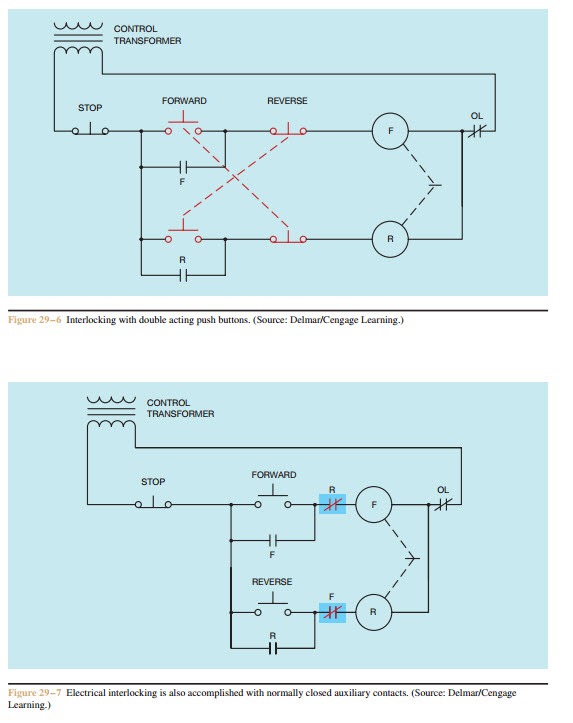
If you have a 120v coil instead of running a line from coil overload l2 you must run coil overload neutral. Otherwise the arrangement wont work as it should be. The wiring diagram will show that two of the motor wires are connected together for 240 volt wiring. Ladder diagram basics 3 2 wire 3 wire motor control circuit duration. Also read about the speed torque characteristics of these motors along with its different types. A motor starter is a combination of devices used to start run and stop an ac induction motor based on commands from an operator or a controller.
Wondering how a capacitor can be used to start a single phase motor. These diagrams apply to intelligent control motorsthat are fitted to the following products pgs ocdeec. Using this method the current is balanced between the 3 poles on the overload. How to wire a contactor and motor protection switch. Open the wiring box cover by removing the screws and verify there are four wires inside the box for wiring the motor. Water pump controller with float switch duration.
Use transformer if you need to. Gamma ec d 5051 diags. You must watch this video. Dol motor starter with 230v contactor coil. 3ph starter3ph motor line voltage control three phase 3ph motor starter controlling a three phase motor rev 08 aug 2006 the above wiring diagram assumes your magnetic starter has a 240v coil. A wiring diagram is a streamlined conventional pictorial depiction of an electric circuit.
Each component ought to be placed and connected with other parts in particular way. How to wire a contactor and overload. 3 phase dol starter control and power wiring diagram. Learn how a capacitor start induction run motor is capable of producing twice as much torque of a split phase motor. Then you connect the 2 motor leads to t1 and t3. It reveals the components of the circuit as simplified shapes as well as the power and also signal connections in between the tools.






.jpg)


