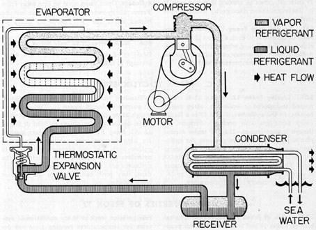
Saturation curve this curve represents what state vapor or liquid and region sub cooled latent heat and superheat the refrigerant is in. The metering device component 3 on this refrigeration cycle diagram is the dividing point between the high pressure and low pressure sides of the system and is designed to maintain a specific rate of flow of refrigerant into the low side of the system.

Uses Of Refrigeration Low Pressure Controls Industrial Controls
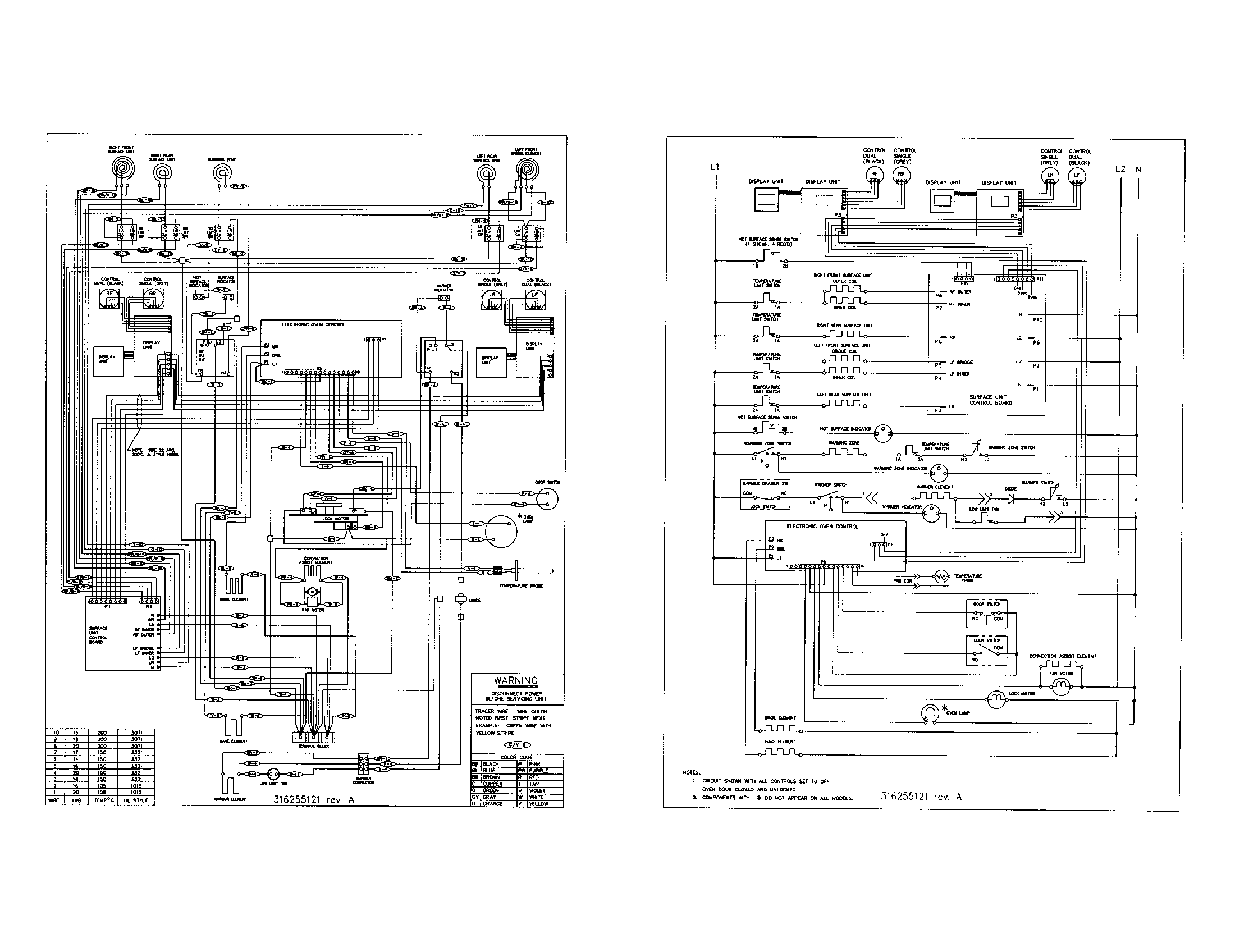
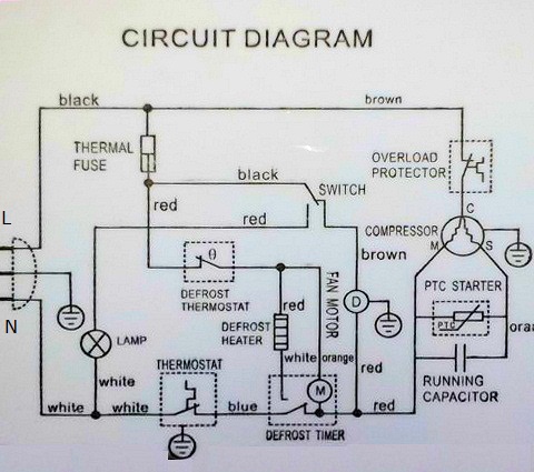
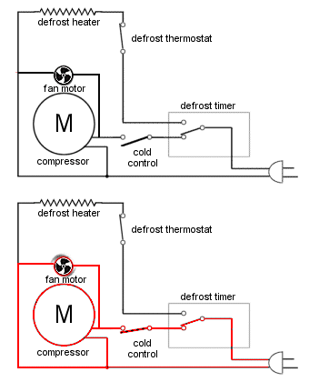
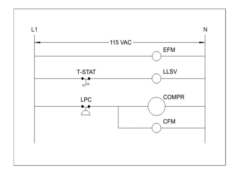
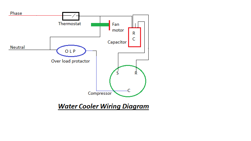
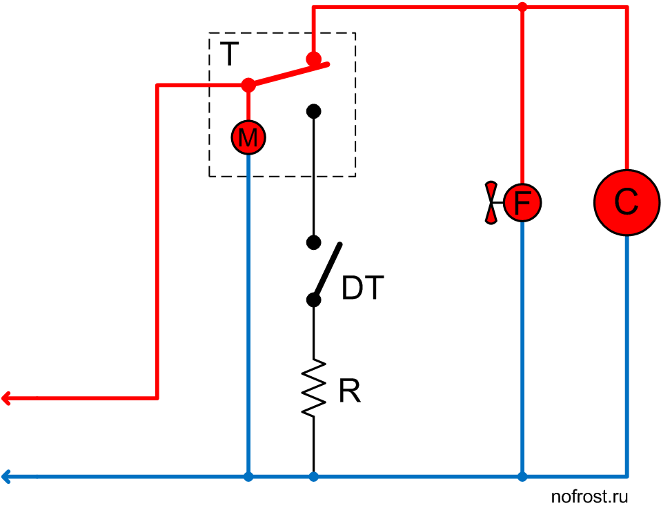
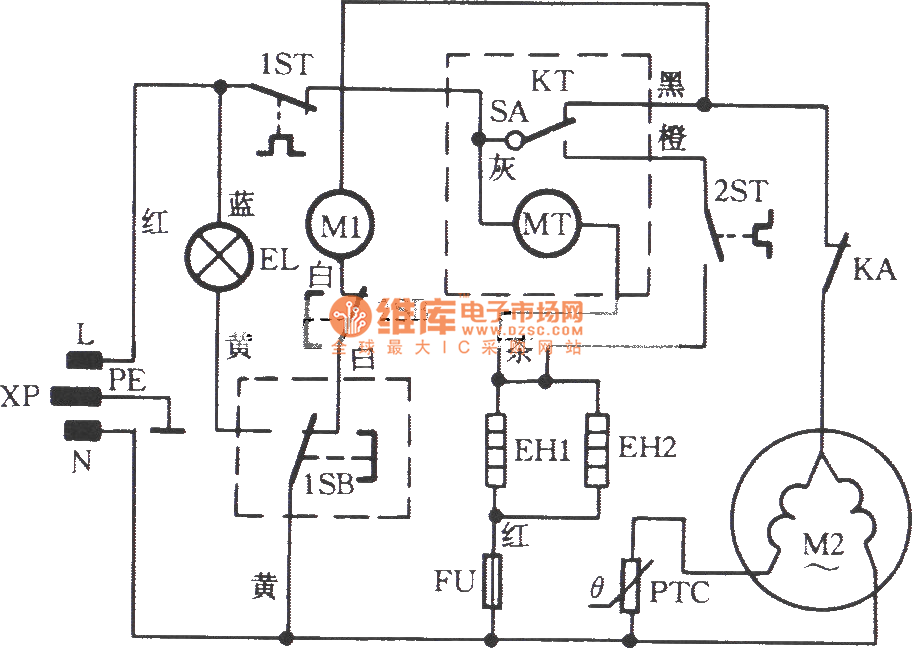
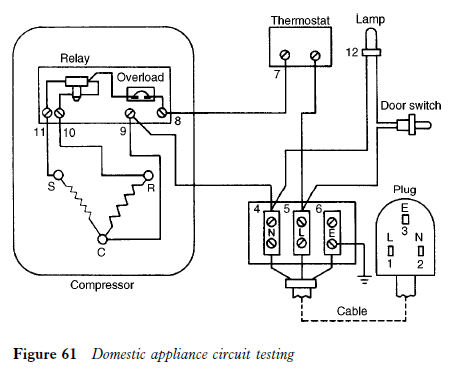
Basic refrigeration wiring diagram. From this point forward ladder dia. Types of wiring diagrams there are three basic types of wiring diagrams used in the hvacr industrytoday. As we can see in the ph diagram below. To remove heat from the air a compressor pushes a refrigerant through copper tubing between a condenser and an evaporator coil. The image on the left shows a small split system for a walk in cooler with 3 electrical devices. Understanding the basic refrigeration cycle diagram also helps us to find subcooled superheat and to troubleshoot refrigeration processes much easier.
First we need to know what loads there are to be controlled. Refrigeration wiring christopher molnar. S33 electrical 108453. Refrigerators and freezers as well as air conditioners heat pumps and other appliances that produce cold use basic refrigeration principles to extract heat from the air. Basic electrical residential wiring duration. Both are located in the appliance.
A compressor condenser fan motor and evaporator fan motor. Lets add a basic control system to a refrigeration system. Diagram of the potential relay part 2. The first and most common is the ladder diagram so called because it looks like the symbols that are used to represent the components in the system have been placed on the rungs of a ladder.


