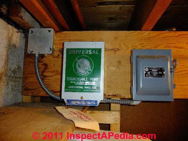
Use this guide to find which circuit is your submersible pump and turn it off. In this video i go over the differences of a 2 wire and a 3 wire submersible well pumpthis is associated with the starting components for the pump and whether they are located inside the motor.

120 240 Volt Wiring Diagram Wiring Diagram
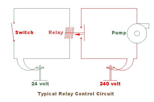
240 volt well pump wiring diagram. 2 wire well pump diagrams are slightly easier to understand and are more straight forward to wire. Here is the complete guide step by step. 240 volt well pump wiring diagram 240 volt well pump wiring diagram every electrical arrangement is composed of various distinct pieces. Dedicated circuit for well pumps the circuit to the well pump is a dedicated circuit designed for the load of the well pump only. The 240 volt pump circuit to your well pump does not have a neutral so you cannot get 120 volts without doing something that would be unsafe. A double pole switch is the safest way to make sure that both lines of the 240 volt circuit power to the pump are turned off.
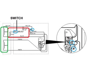
The basic 3 way switch wiring diagram this entry was posted in outdoor wiring diagrams and tagged 2 speed pump 230 volt pump breaker disconnect how to wire a pump pump wiring wiring diagram. Single phase submersible pump control box wiring diagram 3 wire submersible pump wiring diagram in submersible pump control box we use a capacitor a resit able thermal overload and dpst switch double pole single throw. Now look to see if the breaker takes up two breaker spaces or one. Variety of 240v motor wiring diagram single phase. Otherwise the structure will not function as it ought to be. The wiring connection of submersible pump control box is very simple.
Black wires go to black wires and the green wire the ground goes to the ground wire. Two wire well pump wiring diagrams. Hey mcfly you bojo. Wiring a control switch for a 240 volt pump when controlling a 240 volt motor it is best to install a double pole switch for this irrigation pump. Well pumps dont work unwired unless you get power i wire up the well pump to move one step closer to having an ever flowing stream of beautiful well water. Each component ought to be placed and linked to different parts in specific way.
It reveals the components of the circuit as simplified shapes as well as the power and also signal connections in between the tools. Two spaces is a 220 volt system and one is a 110 volt system. The main breaker panel should have a wiring schedule handwritten inside the front door panel. Three wire well pump wiring diagrams. A wiring diagram is a streamlined conventional pictorial depiction of an electric circuit. 2 wire well pump wiring diagram.
