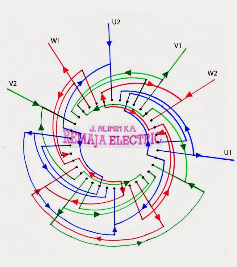
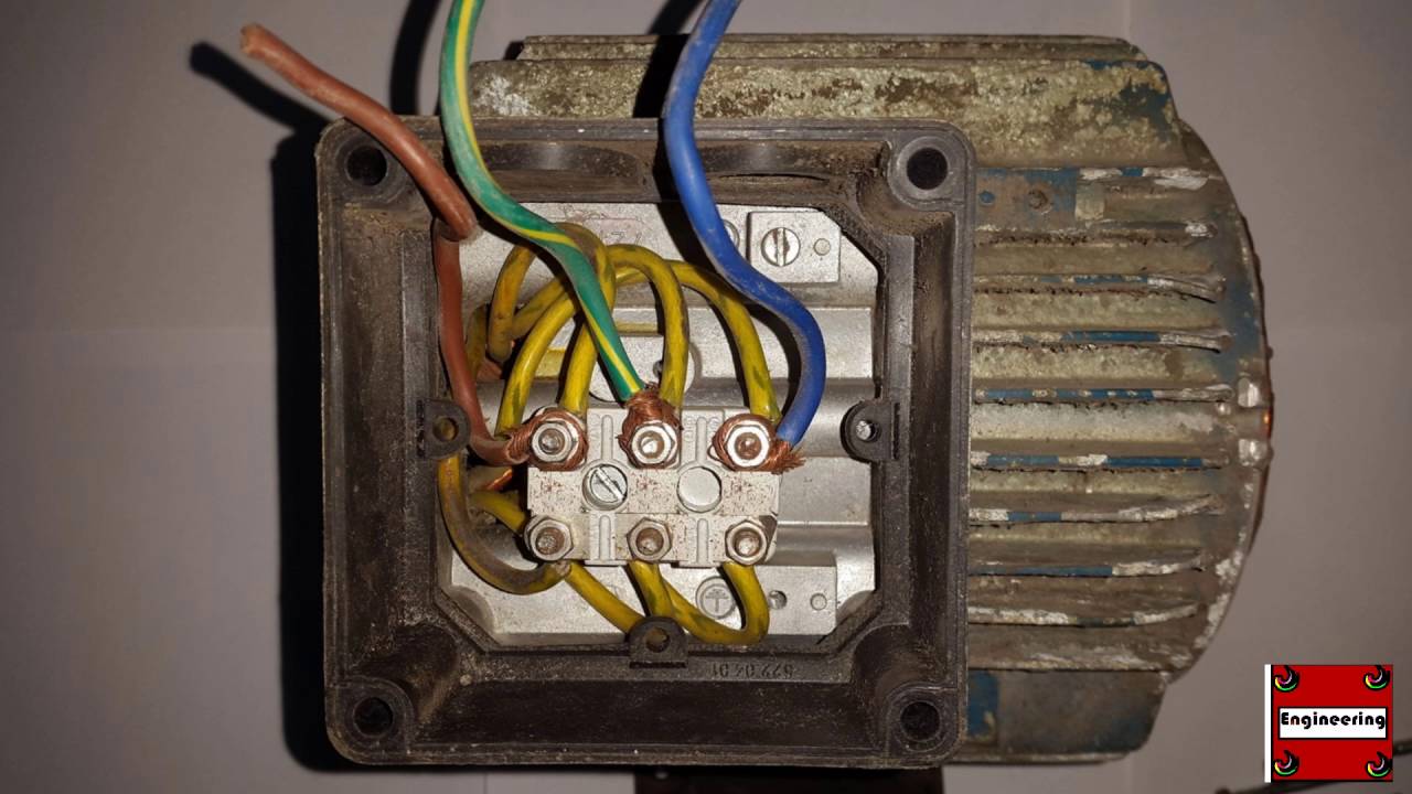
Most electric motors have a wiring junction box typically on the rear of the motor on one side. Electric motor wiring diagram 220 to 110 building wiring representations reveal the approximate areas and also interconnections of receptacles illumination and also irreversible electrical solutions in a structure.

Peerless Electric Motor Wiring Diagram Best Wiring Diagram
220 electric motor wiring diagram. Electric motor wiring diagram 220 to 110 what is a wiring diagram. A wiring diagram is a straightforward visual representation in the physical connections and physical layout of the electrical system or circuit. It shows the components of the circuit as simplified shapes and also the power and signal connections in between the gadgets. Changes in the wiring of an electric motor should only be made after the electric motor circuit has been identified and turned off and tagged. This is where the cord or conduit attaches. Connect the two top terminals on the switch to the l1 and l2 connections in the motors electrical enclosure.
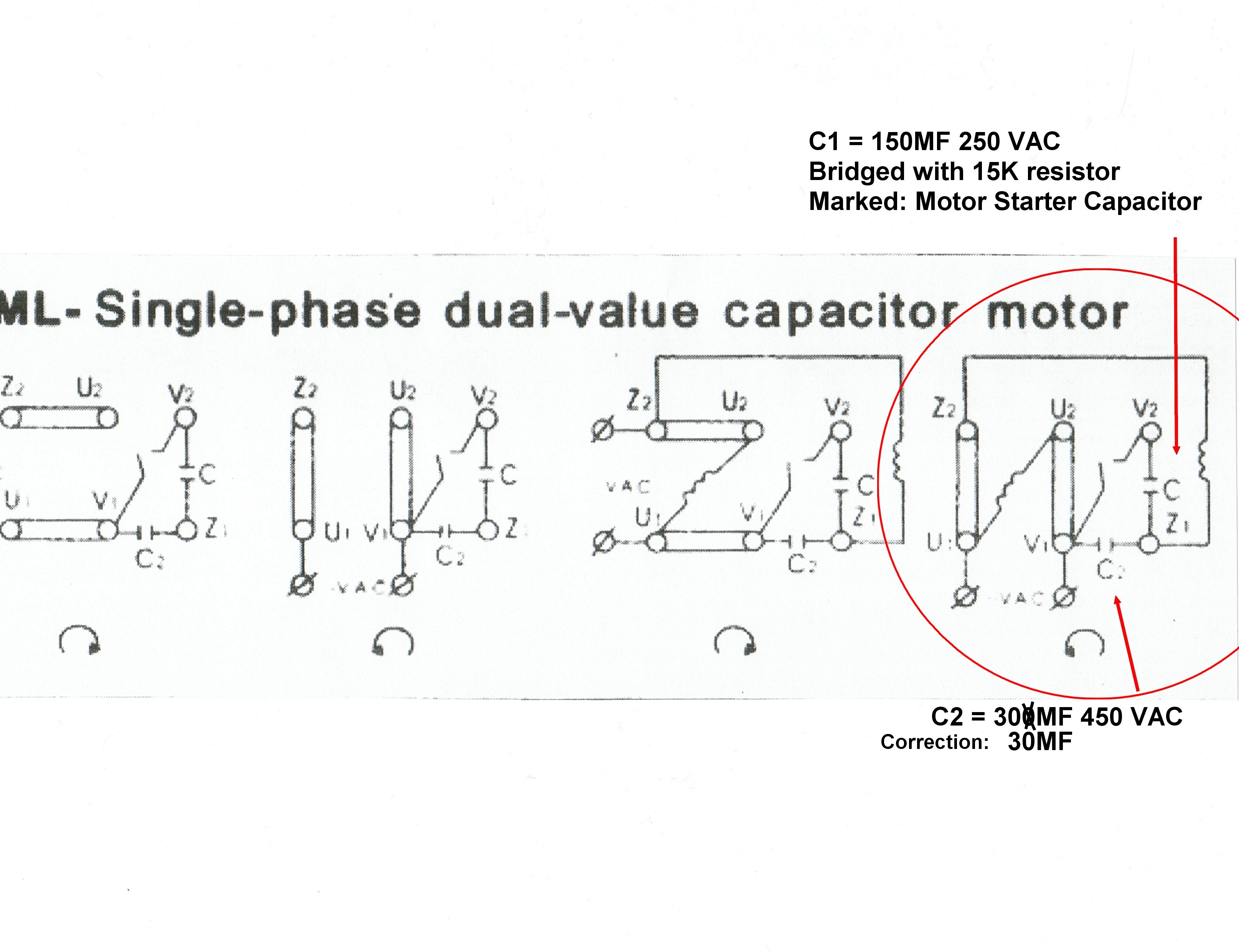
These tips can be used on most electric motor brands such as weg baldor. Click on the image to enlarge and then save it to your computer by right clicking on the image. I have received several requests to cover this topic. Wiring diagram for electric motor with capacitor inspirationa new single phase marathon motor wiring diagram gallery wiring diagram pool pump motor best pool pump wiring diagram. Motors that are designed for 120240 volts. It shows how a electrical wires are interconnected and may also show where fixtures and components might be attached to the system.
This procedure works for electric motors that are able to operate with either 110 or 220 volt power by changing a few wiring connections. Wiring 220 volt boxes and motors is serious business. Each of the two top terminals represents one of the opposite poles of the 220 volt power circuit as do the two bottom terminals. Collection of marathon electric motor wiring diagram. A wiring diagram is a simplified conventional photographic representation of an electrical circuit. I use this for my table saw that i use in different locations to quickly change the motor to run on either voltage.
How dual voltage motors work and how to wire them even without the wire labels. Wiring residential homes with 240 volts is a necessity for powering some heating and cooling equipment as well as some large appliances. In this video jamie shows you how to read a wiring diagram and the basics of hooking up an electric air compressor motor. The 220 volt circuits as they were known prior to the 1960s are now commonly known as 240 volt circuits and 110 volt circuits are now 120 volt circuits. If you want to chip in a few bucks to support more content. Collection of electric motor wiring diagram 110 to 220.


