They all must be between the two 3 way switches. 3 way and 4 way occupancy sensors for indoor motion detector applications electrical question.

Why Are 2 Terminal Screws On Cs415 4 Way Toggle Leviton
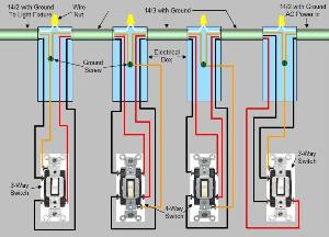
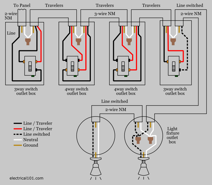
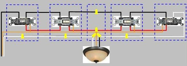
4 way circuit wiring diagram. This is the wiring for a dimmer in a 4 way circuit. This diagram is a thumbnail. Three wire cable runs between all the switches and 2 wire cable runs to the light. 4 way switch wring diagram. All switches in multi way circuits need to be replaced by insteon devices. Insteon installation circuit with 3 or more switches.
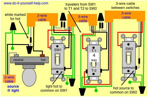
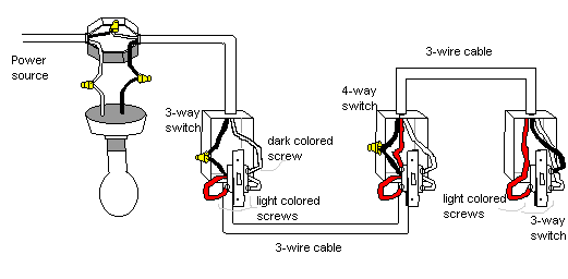
To view it at full size click on the diagram. Attach the black and whiteblue traveler wires entering the 4 way switch box to the in terminals often the top terminals on the 4 way switch black on the left top pole and whiteblue on the right top pole. Unfortunately not all 3 way switches are wired the conventional way. The diagrams below show the conventional wiring for 3 way switches in a 4 way configuration. Watch the 4 way switch video below and pay attention. Look for 4 way switch wiring diagram or step how to wire a four way light switch electrical circuit a 4 way switch is a double pole double throw dpdt switch.
Below is a conventional wiring diagram for a 4 way switch configuration. Click here to access note. I have a three family home unit and in the common stairwell i have a 3 way switch on the first floor a 4 way switch on the second floor and a 3 way switch on the 3rd floor which are all controlling the common stairway lighting. If more than three switches are needed simply place more 4 way switches between the three way switches. How do i wire a motion a sensor to control lights. You can have an indefinite number of 4 way switches in a circuit.
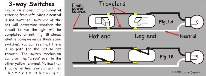
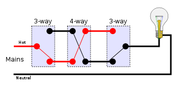
4 way switch wiring 4 way switches provide switching from three or more locations. A 4 way switch is always placed in between two 3 way switches. The switch can be used to control the electricity supplying lights from three locations. 4 way dimmer switch wiring diagram. To make this circuit work a 3 way dimmer can be used in place of one or both of the standard 3 way switches. For complete instructions on wiring a basic 4 way switch see our wiring a 4 way switch article.
Some 4 way switches may have the in and out pairs opposite each other rather than top and bottom. Circuits with 3 or more switches are called 4 way or 5 way etc or multi way. It has 4 terminals or poles and consists of two 3 way switches that are modified. As you will see most 4 way switch wiring is placed between the wiring of two 3 way switches therefore a 4way switch is installed with two 3way. The 4 way is used when you want to control the light or lights from two or more locations. I have a few of the most common ways in wiring a 4 way switch to help you with your basic home wiring projects.
See alternate 3 way switch wiring configuration for another way 3 way switches may be wired. If you understand how to wire a 3 way switch youll have no issues with a 4 way switch. Traditional switches also use traveler wires to get electricity from one switch to the next in a multi way set up. A 4 way switch wiring diagram is the clearest and easiest way to wire that pesky 4 way switch.
Gallery of 4 Way Circuit Wiring Diagram