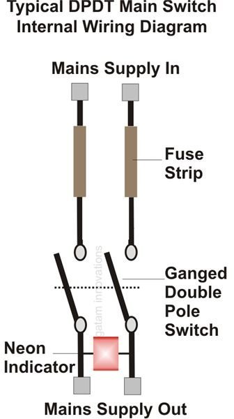
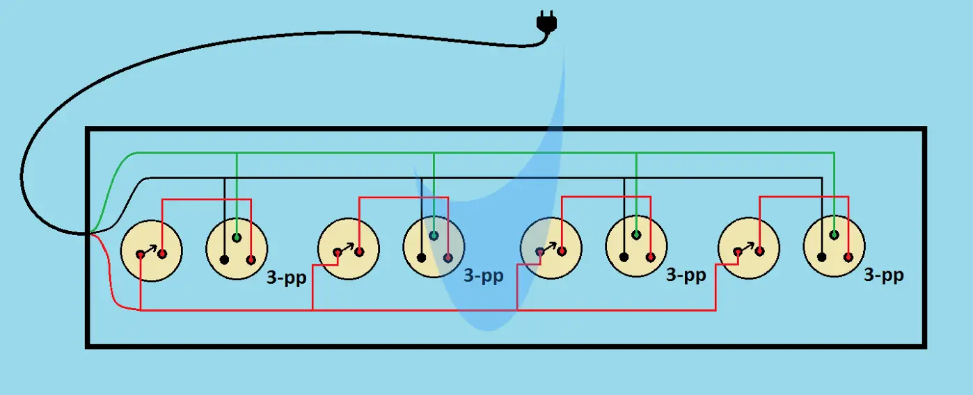
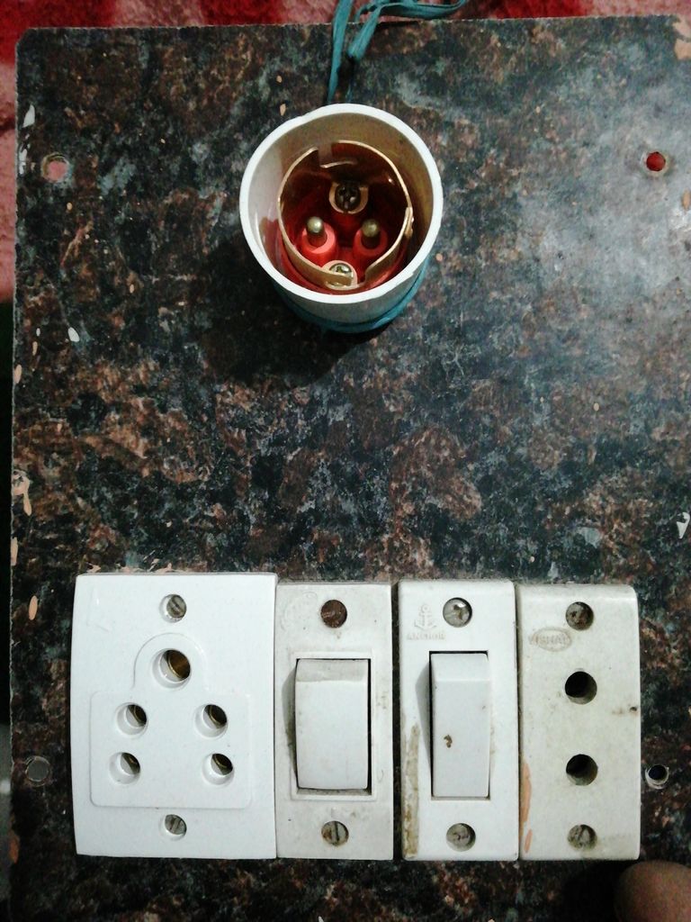
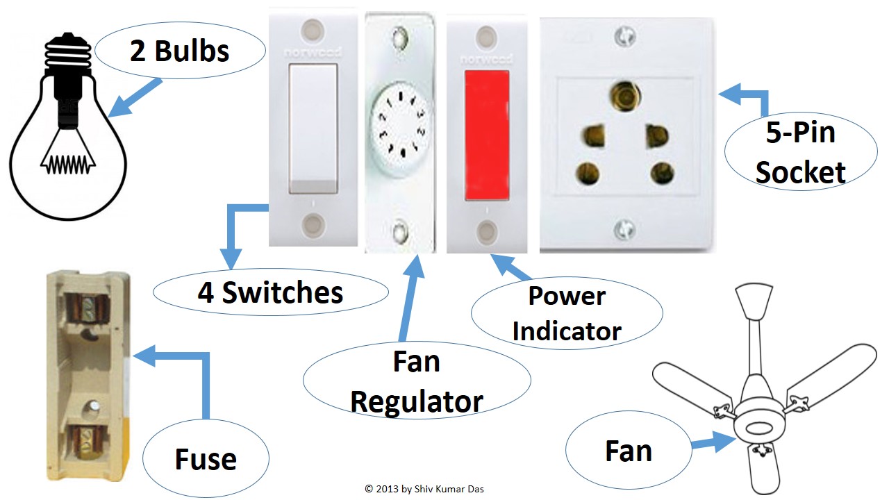
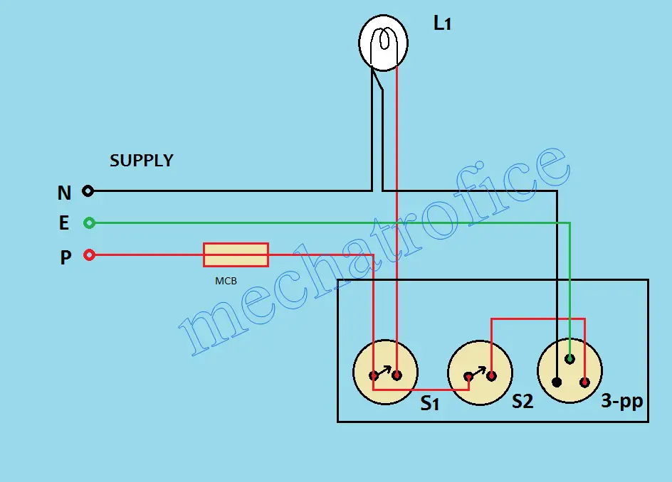
How to make an electric extension board 8 socket 1 switch 1 indicator 1 fuse electric board wiring duration. In the below wiring diagram one pole of the both spst single pole single throw switches s1 s2 are connected to the phase line of the supply.
How To Wire A Switch Box Electrical Switch Board Connection
1 switch 1 socket 1 indicator connection diagram. Fixture wiring exits the switch box. Understanding toyota wiring diagrams worksheet 1 1. The other pole of switch s1 is connected to the lamp. Circuit j5 1 1 17 18 10 17 18 10 1 1 25 8 2. Describe the meaning of the sd in diagram component t. Describe the meaning of the 2 in diagram component s.
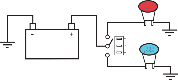
The switch terminals use a clamping mechanism as opposed to a screw connection in order to. Describe the meaning of the c13 in the diagram component q. Describe and identify the diagram component u. The switch terminals are clearly numbered with a corresponding wiring diagram on the side of the switch to make installation and connection as simple as possible. Switch wiring shows the power source power in starts at the switch box. 2 socket 2switch 1 indicator connection2 5 pin socket 2 switch connection duration.
The black wire power in source attaches to one of the switch screw terminals. The given circuit is a basic switchboard wiring for a light switch and 3 pin socket with control switch. Sinha electricals 77593 views. Indicator connection1 socket 1switch 1indicator connection74 board connection. When the switch is pulled out. 1 circuit diagram 17 18 10 1 connector part 16 3 3 14 5 circuit diagram 6 14 31 4 jajjjk j2 circuit j1j3j4j5 228 8 3 17 18 58 2 2 10 13 circuit diagram ja 331 4 15 12 6 5 8 3 symbol legend definition jk jj 1 17 18 10 17 18 10 circuit diagram 14 1 3 1311 circuit 1311 13 11 sym.
Identify the light socket containing the 3 warning light bulbs. One way switch with indicator socket switch tested and approved to iec sans60669 1. The socket with the gray and black wires contains the column shift indicator light and will not be used. The composite diagram is shown here. The black wire power out wiring attaches to the other switch screw. Describe the meaning of the g w in diagram component r.
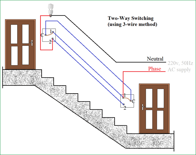
Explanation of wiring diagram 1. In this article simple two way light switch connection described with neat circuit diagram and wiring details. Making onoff light from two end is more comfortable when we consider stair case two way light control is simple and easy to construct. 1 power for the flasher is shifted from term 15 to 30 which is live all the time. From late 68 thru 71 the 6 wire turn indicator switch was married to a complicated hazard switch in order to do away with the expensive 9 terminal flasher. The socket with the pink and tan wires is the brake warning light.
Share on tumblr 2 way light switches are helpful to turn on or turn off light from different end locations. Remove the tan wire from the light socket and install a single male disconnect terminal. How to wire up a switchboard. Circuit electrical wiring enters the switch box.
