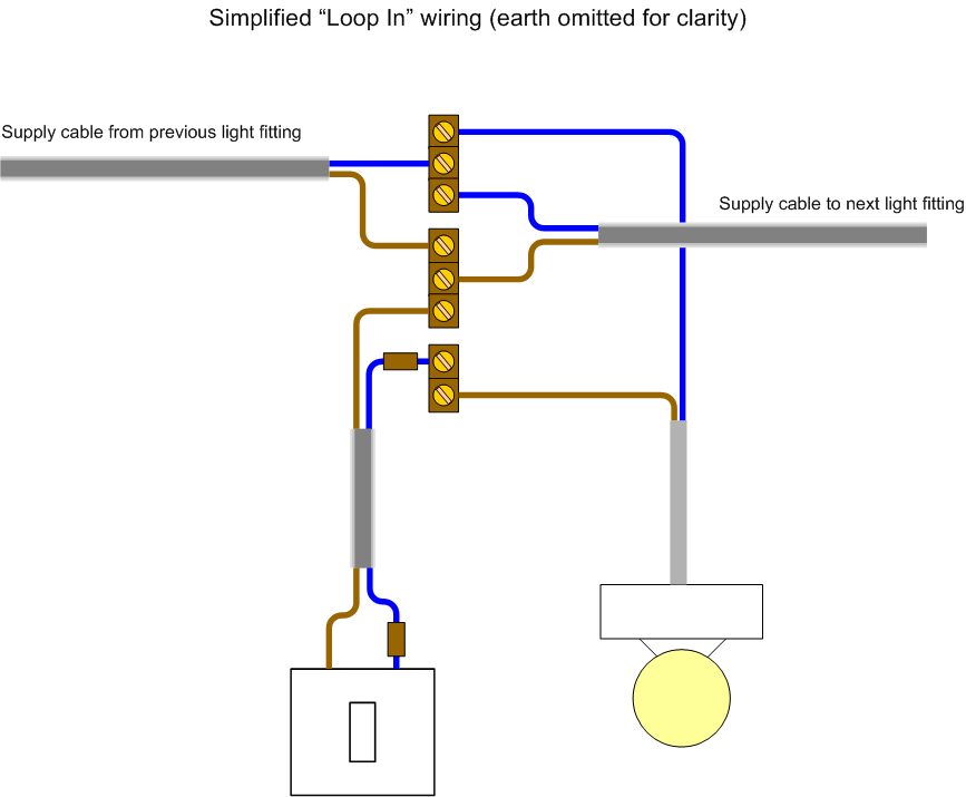
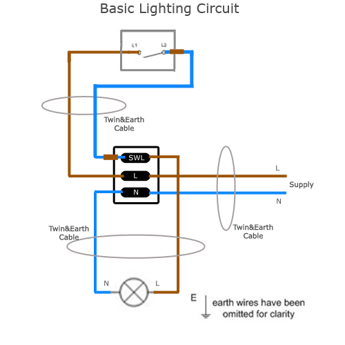
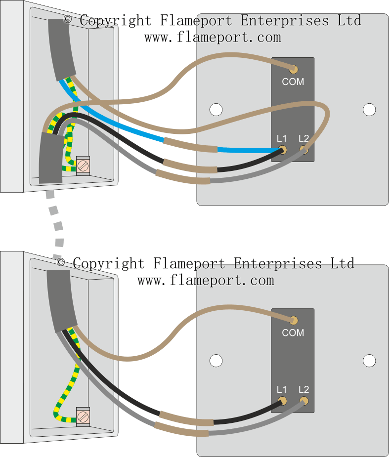
Connect the line brown wire to the l terminal together with the supply cable line wire and connect the blue wire with the brown slewing to the swl terminal together with the lamps line wire. The cable going to the light switch is connected as follows fig 2.
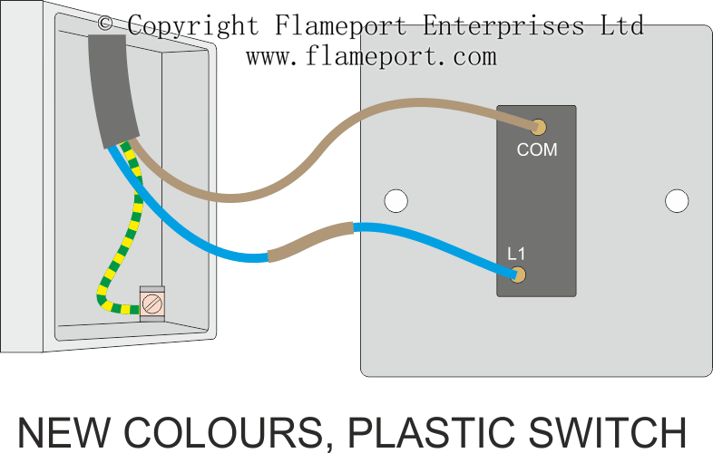
Adding An Extra Light From A Light Switch
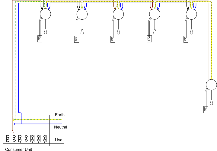
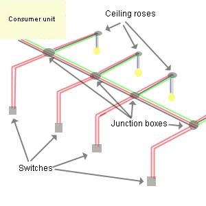
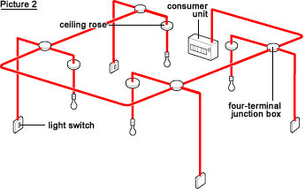
Wiring a lighting circuit uk. Ring or ring final circuit rfc a ring circuit is a uk standard means for wiring domestic and other light commercial premises not often seen elsewhere in the world. The second system in popular use is the junction box circuit or system. The permanent live wire is wired into the switch and the switched live into the switched live terminal. The live is interrupted by the switch wiring and the circuit is carried on to the next junction box. We have and extensive collection of common lighting arrangements with detailed lighting circuit diagrams light wiring diagrams and a breakdown of all the components used in lighting circuits. A cable is run from the junction box to the light usually via a ceiling rose.
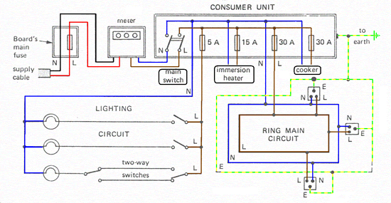
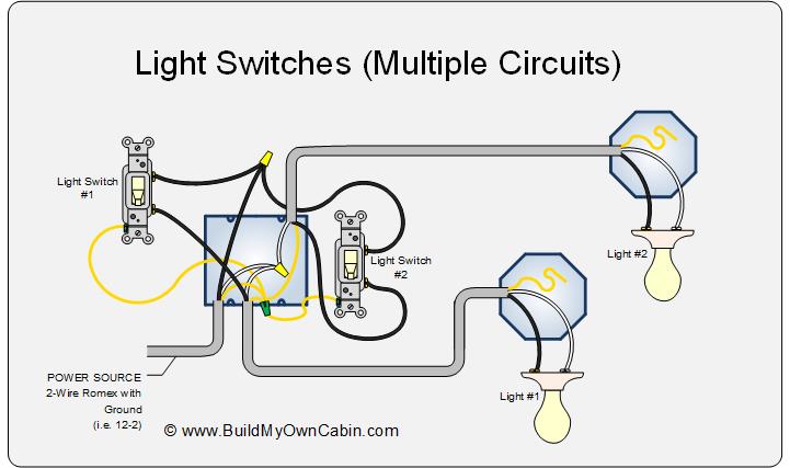
You can also see that another live and neutral wire go to the next light switch. The neutrals are connected together using a terminal connector. Instead of taking the feed wire from the consumer unit to the ceiling rose it is taken to the switch. This is an alternative way of wiring a lighting circuit. The white wire is marked black on both ends to identify it as hot. In modern domestic properties in the uk the main electric lighting circuits are separate from the power ring main circuit.
A one way light switch is quite easy to wire up. Two way switched lighting circuits 2 3 way switched lighting circuits loop at switch lighting circuits lighting circuit diagrams for 12 and 3 way switching series and parallel circuits adding an extra light from a light switch wiring for a single loft or garage light motion sensor wiring with switched override feature. Line diagram of a one way lighting circuit using in line method fig 1. Each house should ideally have at least two lighting circuits. Here you can see there is a cut in the line wire connected to lamp 3 so the bulb is switch off and the rest circuit is working. Type one lighting circuit.
Power is taken from the consumer unit to the first junction box. The red wire from the feed cable is connected to the top terminal the red wire going to the light is connected to the bottom terminal the black wires from both cables are connected together in a plastic terminal block and the earth. In effect it is a radial circuit whose final termination is made back to the originating distribution board rather than at the last outlet or device serviced. One way lighting circuit using in line switching. This circuit is wired with a 2 wire cable running from the light to the switch location. All the light wiring diagrams are available in the old and the new cable colours to avoid confusion.
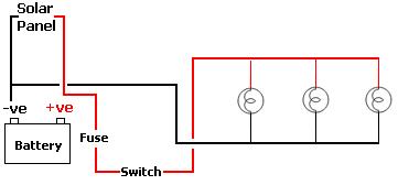
Each protected by a 5 amp fuse or 6 amp trip in the consumer unit. The neutral from the source is connected directly to the neutral terminal on the light and the source hot is spliced with the white loop wire. Do not forget to use brown slewing on the blue wire. Always isolate any electrical circuit before working on the circuit. Another major defect of series lighting circuit is that as all lamps or bulbs are connected between line l and neutral n accordingly if one of the light bulb gets faulty the rest of the circuit will not work as the circuit will be open as shown in fig below.


