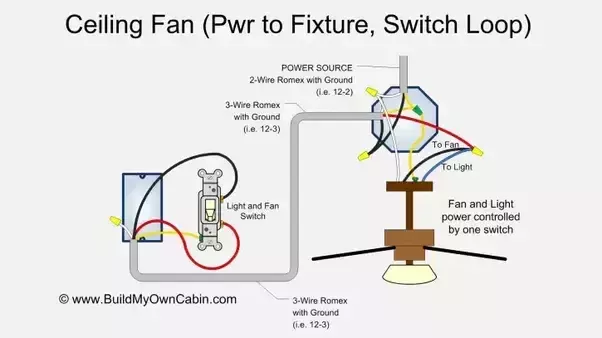
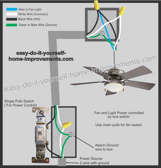
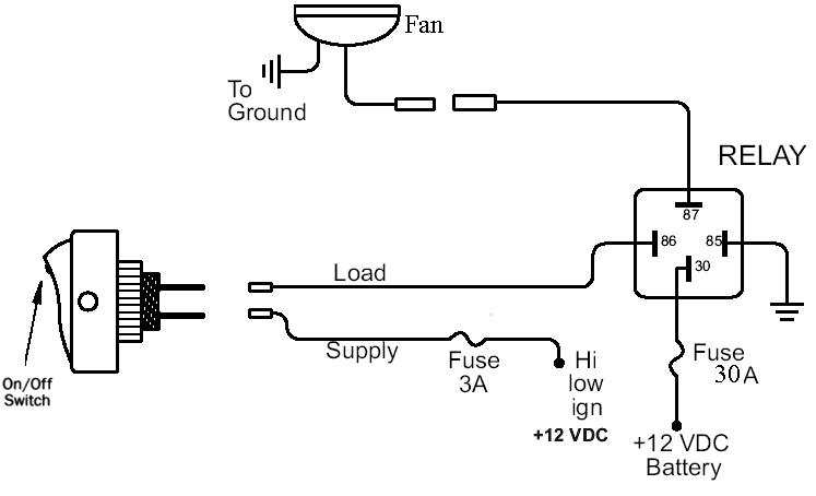
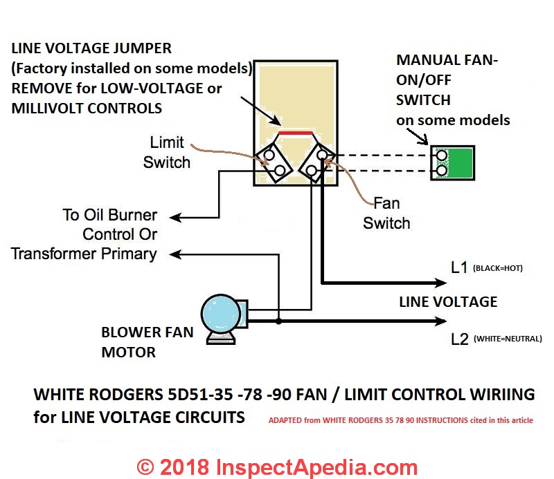
It reveals the elements of the circuit as simplified shapes and the power and signal connections between the tools. With double switch wiring a fan with a light is connected to a double wall switch that controls power to the fan and the light separately.

Wiring Diagram For Light Switch To Outlet
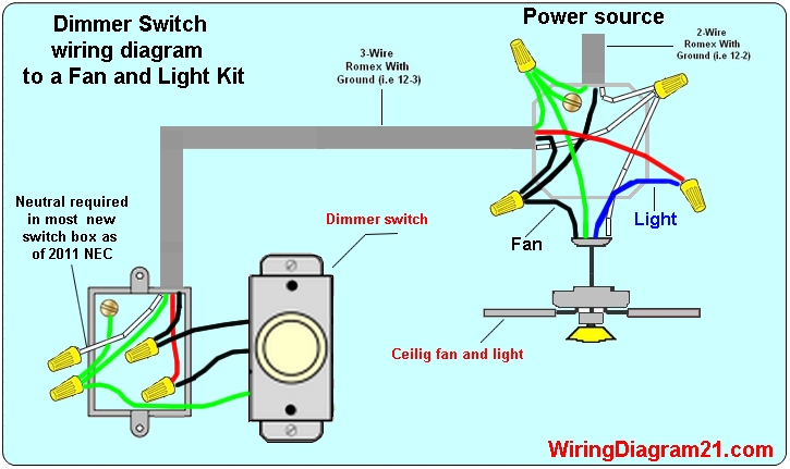
Wiring a fan switch diagram. The neutral from the source is spliced directly to the white wire on the fan kit and the cable. Collection of 4 wire ceiling fan switch wiring diagram. A wiring diagram is a streamlined standard pictorial depiction of an electrical circuit. Line voltage enters the switch outlet box and the line wire connects to each switch. The fan has power when the switch is on while the fan speed and the light if the fan has one are controlled by pull chains on the fan itself or by a remote control device. This wiring arrangement allows for lowering the lights with a dimmer and controlling the fan with the built in pull chain.
Whether you are looking to wire a ceiling fan with lights to one power switch or add a fan in a room without a switch source this guide will teach you how to wire a ceiling fan using four common scenarios and the best wiring methods. The source is at the ceiling outlet box and 3 wire cable runs from there to the switch box. Wiring ceiling fans can seem complicated but the task really just depends on the type of fan you are installing and how you want it to operate. Ceiling fan dimmer switch diagram. With such an illustrative guidebook you are going to have the ability to troubleshoot stop and total your projects with ease. Ceiling fan 3 way switch wiring diagram you will want a comprehensive expert and easy to know wiring diagram.
Switched lines and neutral connect to a 3 wire cable that travels to the lightfan outlet box in the ceilingthe fan control switch usually connects to the black wire and the light kit switch to the red wire of the 3 way cablein this diagram the black wire of the ceiling fan is for the fan and the blue wire.
