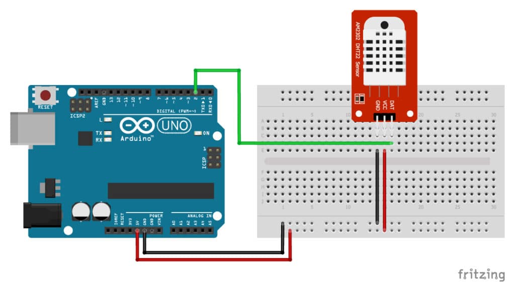
A green led indicates sensor and cable integrity. They show the diameter of each wire using a label placed at some point along side its drawn line 1 08.

Pdf 270 Mini Electronics Project With Circuit Diagram
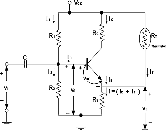
What does g 1 0 indicates on wiring circuit diagram. 3 connection designation relay control module on relay panel shows the individual terminals in a multi point. Wiring sold for electrical projects often carries labeling to help you choose the right product for your needs. Your dometic fridge does not come from the factory with adequate boiler temperature protection. Dometic control box wiring. How ever i knew the fuse also powered the. I chose this wire based on the wiring diagram which showed fuse 24 in the ip fuse box feeding voltage to the front axle motor.
This symbol indicates a dashed wire and a circle with cross out. See 3 for wiring. Also it is a good idea to either use an in line fuse or an arp circuit breaker in line with the power supply to the control box. 10 br s33 05 sw t4521 30 05 ro 10 ro 05 ro 114 e11 6 4 17 t4529 t62 05 sw j362 14 16. Assuming a normal diode on the circuit board relay a is affected by a problem in the circuit containing the pto switch and left and right steering switches. 0 1 0 10 mvg 0 2 5 25 mvg 0 5 0 50 mvg 1 0 0 100 mvg see note 2.
Circuit containing the pto switch and left and right steering switches. Letters numbers and wording on wiring labels tell you important information such as the wire material the size of the wire and the type of insulation used on the conducting wires. The neutral wiring in a multi wire branch circuit may get overloaded when a single 120 vac inverter is directly connected to both the hot legs l1 and l2 on the 120 240 vac service entrance panel load center distribution panel as in shown in fig. Wiring diagram layout wiring diagram layout i. 2 arrow indicates wiring circuit is continued on the previous andor next page. Automotive wiring diagrams and electrical symbols.
In the event of sensor failure the led extinguish. Present on terminal c circuit 241 brown wire. It is also affected by a problem in the circuit containing the parking brake switch and seat switch. Going this far without first checking the fuse could turn out to be pretty embarrassing if the problem was simply a blown fuse. 1 0 8 6 tdr 4 2 1 0 8 6 tdr relay 2 4 2 rec 1 0 6 relay 1 relay 3 legend gnd hvtb htr equipment ground high voltage term. The detection circuit is responsive to true rms vibration but the output may be scaled either to peak or rms units.
These can take some effort to locate on fold out map type diagram. Block heater rec tdr recitfier time delay recitfier field power wiring marked terminal plug and receptacle schematic diagram single supply circuit yel blu blk relay 3 22 vdc coil t d r relay 2 22 vdc coil t d r brn brn gry. At first glance the repair diagram may not convey how the wires use many colors and diameters.


