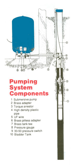
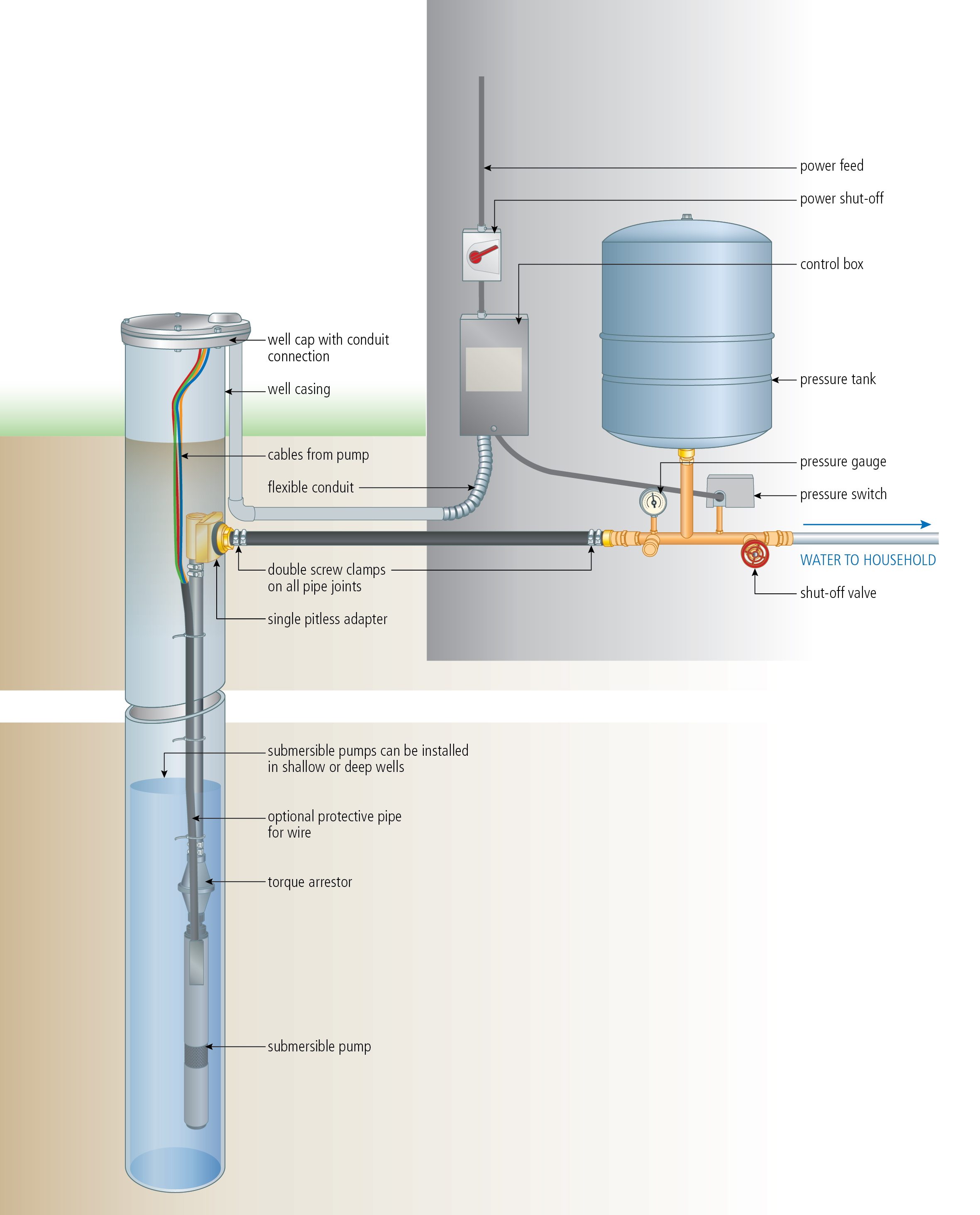
Well pump wiring diagnosis repair. Pressure switches are used on water pumps for the accurate control of the pump as it produces pressurized water.

Water Well Submersible Pumps Wiring Diagram Diagram Base
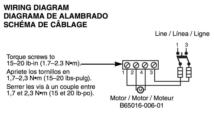
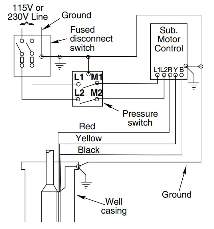
Well water pump wiring diagram. Ultimately using some simple electrical tests the homeowner traced the water pump problems to a nicked well pump wiring circuit wire. A wiring diagram is a simplified traditional pictorial representation of an electric circuit. A submersible pump can be either two or three wire regardless of the voltage coming from the panel so start at your pump and follow the conduit back. Collection of 3 wire submersible pump wiring diagram. Well pump installation can be dangerous when dealing with water and electricity so extreme caution must be taken. Before getting started look up your owners manual and read over the precautions and all other warnings before beginning the installation.
However with the pressure switch the pump can be adjusted to turn on and off at predetermined settings to control the pump and subsequent pressure. Without the use of the switch the water pump would always be on or off. It shows the parts of the circuit as simplified forms and the power and also signal links in between the devices. If it runs straight to the pressure switch it is a two wire. The manual will contain important safety precautions wiring diagrams tools required for assembly proper grounding. Variety of 4 wire well pump wiring diagram.
3 wire submersible pump wiring diagram well pump wiring diagram and 3 wire submersible. If the conduit runs into a control box before continuing to the water pressure switch chances are you have a three wire pump. Click on the image to enlarge and then save it to your computer by right clicking on the image. This article describes troubleshooting a submersible well pump that was causing tripped circuit breakers and that pumped water only at a slow reduced rate and pressure.


