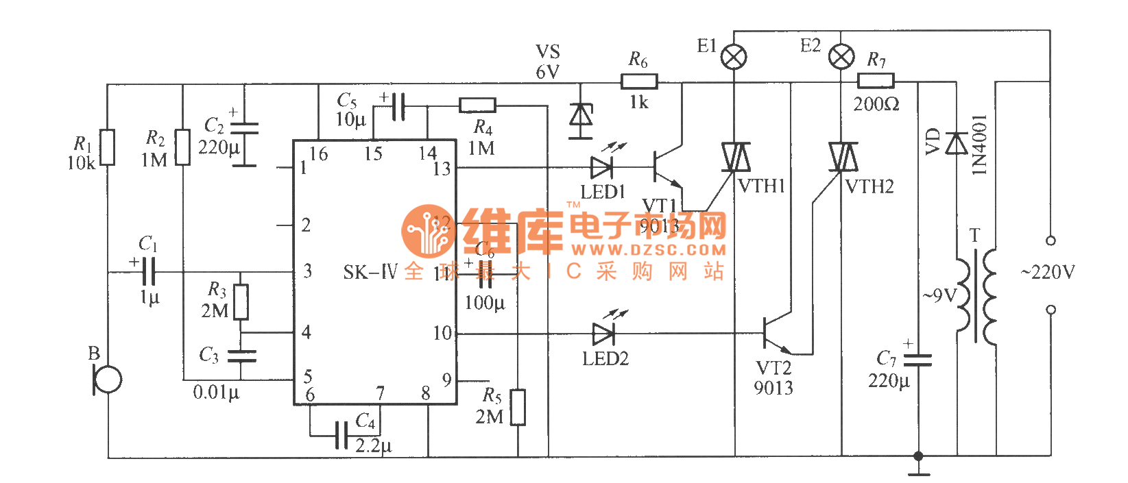
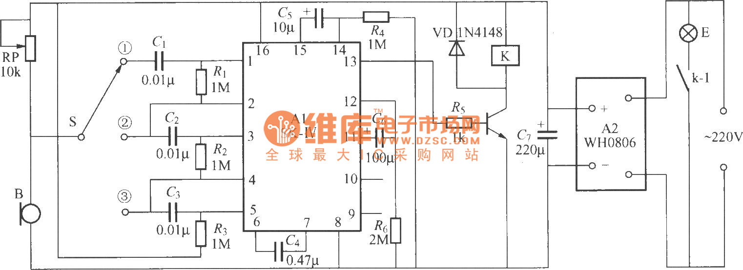
The output switch of this circuit is act by a relay. This circuit uses an mc2830 to form a voice activated switch vox.
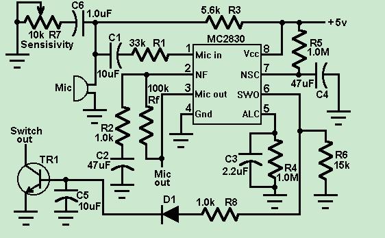
Voice Activated Switch Control Circuit Circuit Diagram
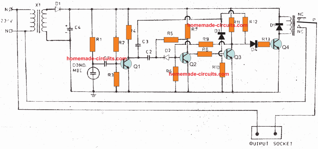
Voice switch circuit diagram. This schematic diagram below show a circuit of vox box voice operated switch. The circuit was drawn using fritzing software. In a noisy environment the switch is often triggered by noise or the activation sensitivity must be turned down. This circuit overcomes this weakness. This is the circuit diagram of a voice operated relay. It similar with sound activation switch circuit which will turn on and turn off connect and disconnect the switch depending on the sound input.
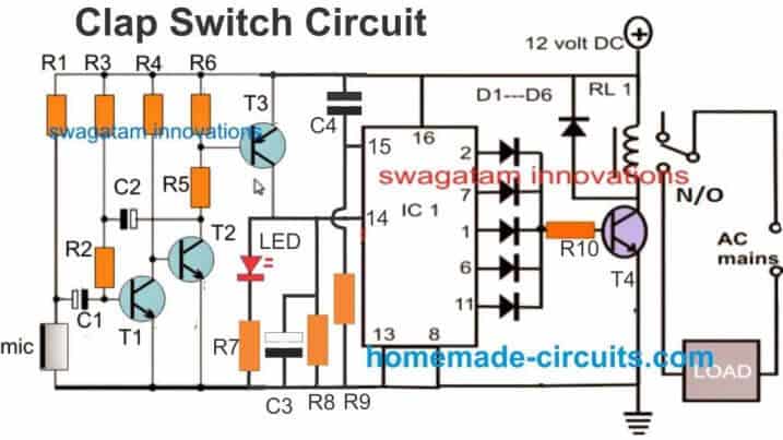
The post details 3 simple sound activated relay switch circuits which can used as a module for any system that might be assigned to trigger by detecting some kind of sound pressure levelor simply applications such as a voice activated alarm security circuit. The connection opens the circuit. The call is routed through the switch at your local carrier to the party you are calling. Whistle detector arduino circuit diagram. The vox switching threshold is 600mv on r2 and the maximum input voltage must not be higher than 40vpp. This circuit overcomes this weakness.
The actuating threshold is set thru the volume potentiometer of the amplifier which command the vox circuit. 1 relay 12v dc 2 resistance 10k ohm. The phone at the other end rings and someone answers the call. The complete circuit diagram for the arduino whistle detector switch circuit using sound sensor is show below. All the connections are made as per the circuit diagram above. This circuit consist of a schmitt trigger a relay driver and microphone preamplifier.
A traditional vox circuit is unable to distinguish between voice and noise in the incoming signal. In a noisy environment the switch is often triggered by noise or the activation sensitivity must be turned down. The microphone preamplifieru1 receive input signal which will be amplified. A connection is made between your telephone and the other partys line using several interconnected switches along the way. After making the necessary connections we have to switch on the power supply to the circuit. This circuit uses an mc2830 to form a voice activated switch vox.
We will now see the working of the project. Threshold control r8 is fed by the amplified signal. In this project a simple voice activated home automation system is designed. The sound sensor and the relay module is powered by the 5v pin of the arduino. Vox is a voice controlled switch used often for microphones replacing the classic switching button. A traditional vox circuit is unable to distinguish between voice and noise in the incoming signal.
Voice commands are used to control different appliances. Hello my loved people today i would to show you about how to make automatic switch on the light by voice or sounds automatic switch circuit.


