A ups bypass switch is a non essential addition to an uninterruptible power supply system that while not integral to ups operation is definitely useful in the event of maintenance or repair. De nouvelles réalités pour linformatique.

Apc Ups Wiring Diagram Apc Gtupuhms Mge Galaxy Kva Associates
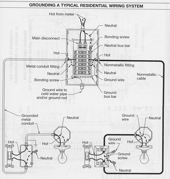
Ups wiring schematic. Now according to the below ups connection diagram connect an extra wire phase to those appliances where we have already connected phase and neutral wires from power house db ie two wire as phase live as shown in the below fig. Ups schematic circuit diagram dc ac is below figure ups showed. Wiring diagram for ups bypass switch fresh fine ups wiring diagram. What is ups and its application. Wiring diagram for ups bypass switch new rotary switch wiring. Wiring diagram for ups bypass switch new rotary switch wiring just whats wiring diagram.
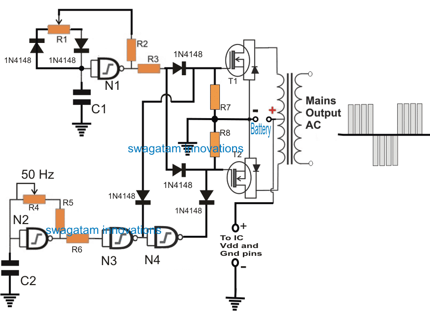
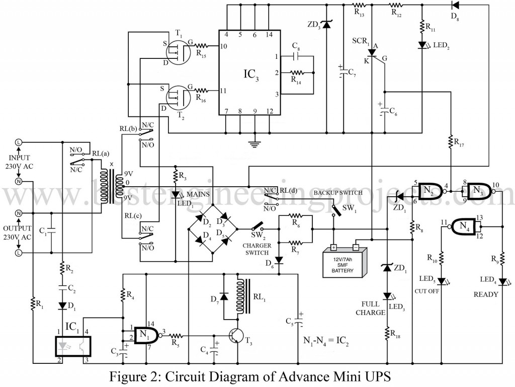
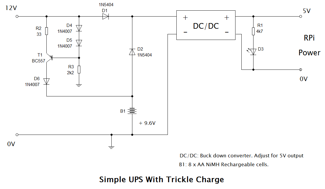
This power supply circuit system consists of a transformer a bridge rectifier and an electrolytic capacitor. The circuit drawn pertains to a regular industrial ups uninterruptible power supply which shows how the batteries take control during an outage in electrical supply or variation beyond the normal limits of the voltage line without disruption on the operation providing a steady regulated output 5 volts by lm7805 and an unregulated supply 12 volts. Cyberpower earns 5 star rating in the 2020 crn partner program guide. Small ups 6v backup. Electric guitar pickups bass guitar pickups acoustic guitar pickups and accessories emg active passive pickups over 25 years of active pickup technology the original active pickup. Ups is an abbreviation of uninterruptible power supply source.
An inverter or ups is a device that typically provide power backup in emergency to a device or load when normal electricity power source is down. The core items you need in order to be protected in the event of power failure are a ups and a battery to supply the power under standard operation this should be all that is required. And there is a zener diode for controller the output power transistorbd135 npn of this circuit and will be determined at a constant voltage of 75 volts. Related electrical wiring tutorial. A wiring diagram is a kind of schematic which makes use of abstract photographic signs to show all the affiliations of components in a system. Ups inverter wiring diagram with auto manual changeover switch system.
Circuitry diagrams are made up of two things. Introduction to automatic inverter ups wiring. New realities for it. Power failure and emergency breakdown may happen any time due to short circuit damage to electric transmission lines substations or other parts of the distribution system storms and other bad weather conditions etcin this case emergency generator or battery backup can be used to restored the electric power to the home and other connected. A wiring diagram is a type of schematic which uses abstract pictorial symbols to reveal all the interconnections of elements in a system.


