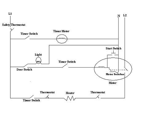
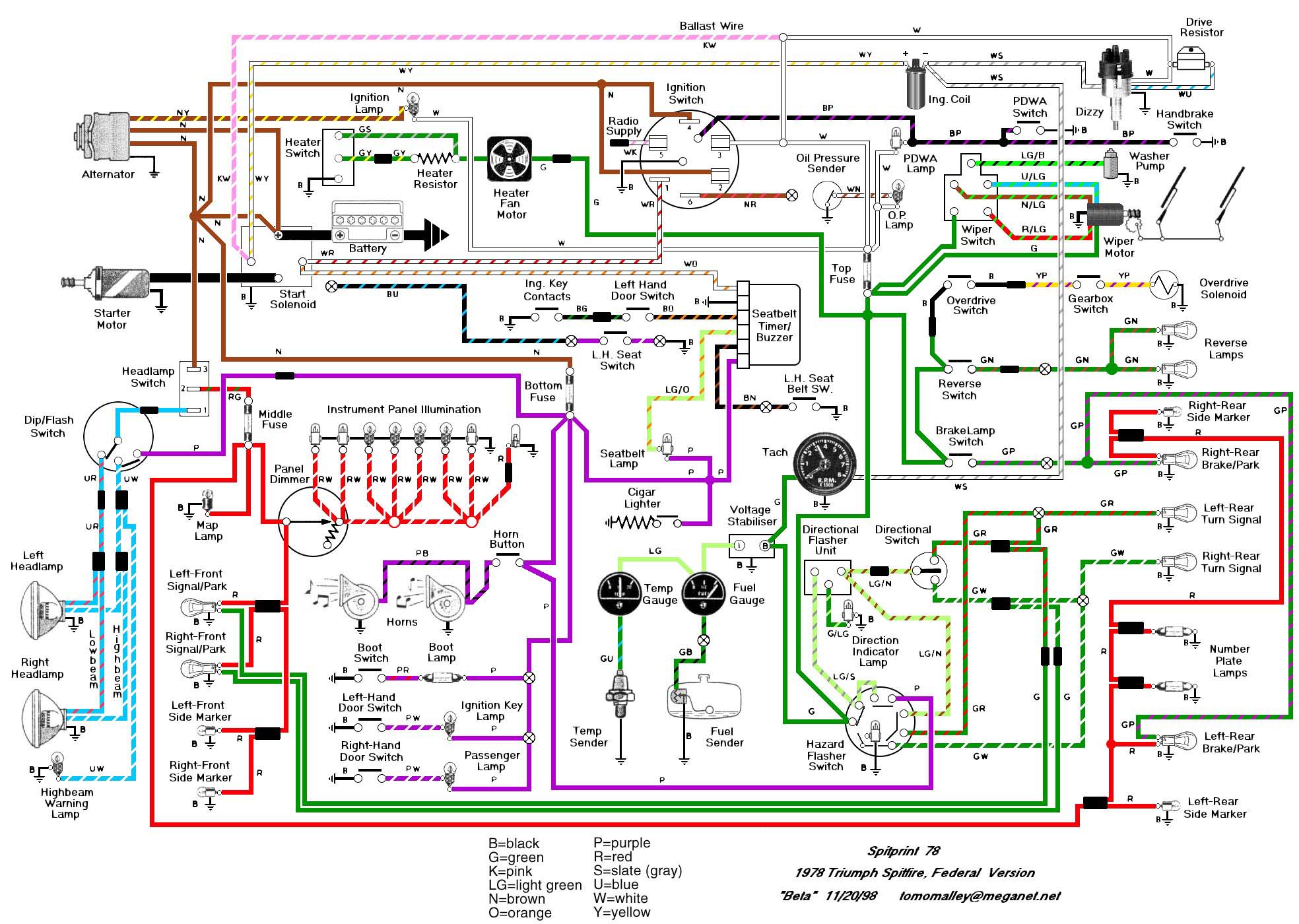
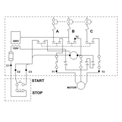
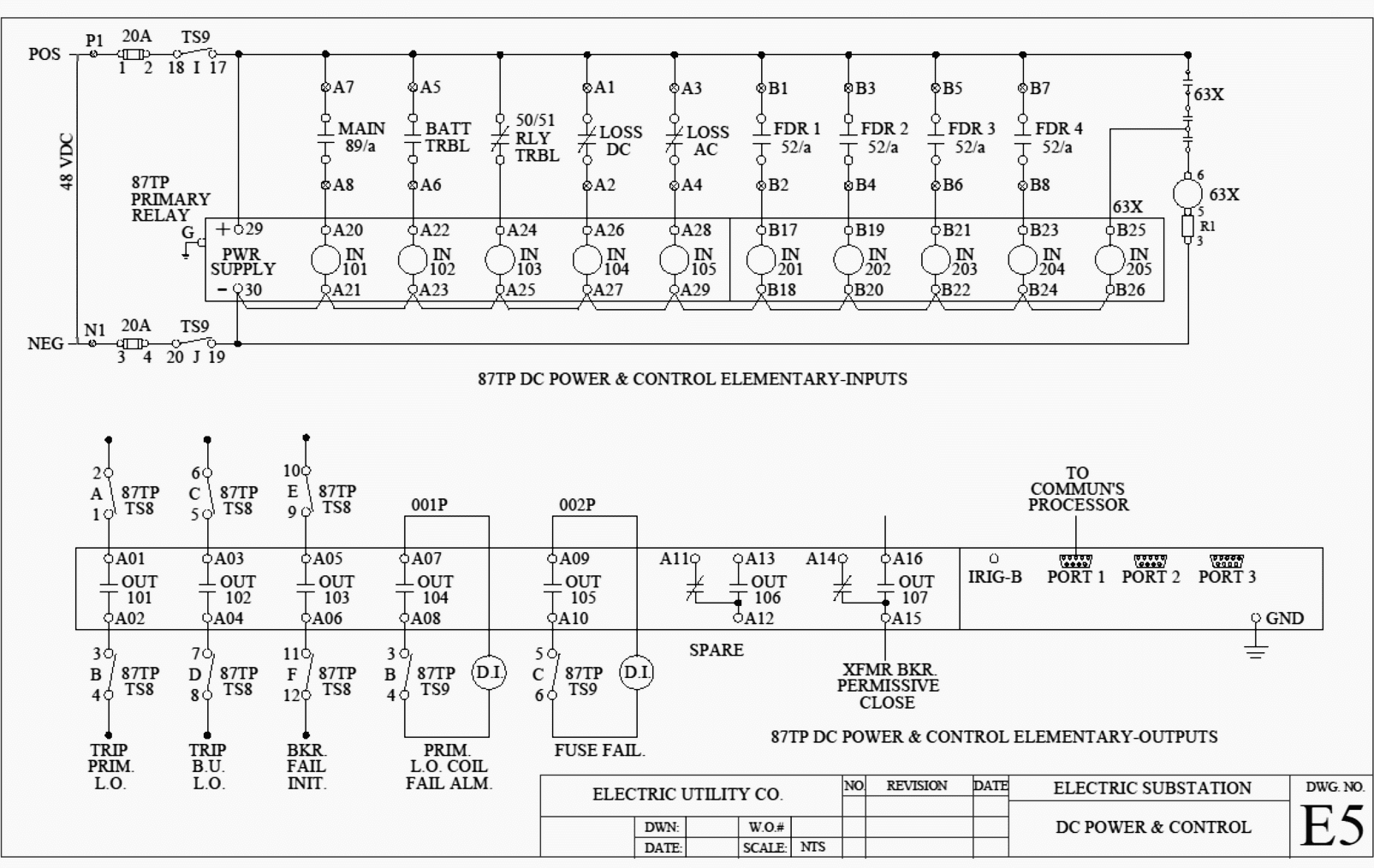
Understanding which components are which on a schematic is more than half the battle towards comprehending it. Especially if you start messing around with building little electronics projects.

Wiring Diagram Everything You Need To Know About Wiring Diagram
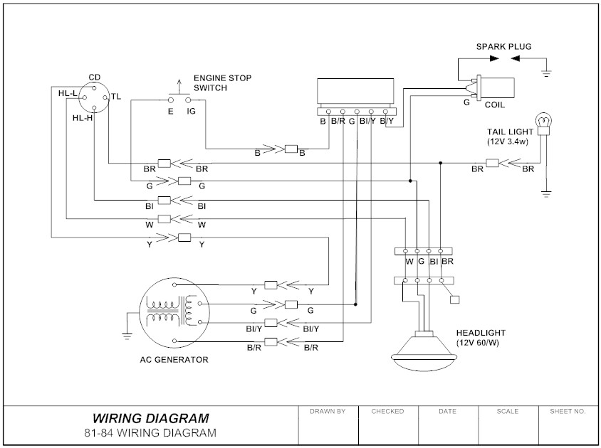
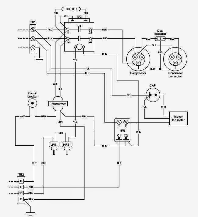
How to read a schematic wiring diagram. Wiring diagrams or layouts illustrate the physical connections or wiring between components. Nets nodes and labels. Now all that remains is identifying how all of the symbols are connected together. Knowing how to read circuits is a very useful skill that will help you out all the time. Each of the lines are wires. This instructable will show you exactly how to read all those confusing circuit diagrams and then how to assemble the circuits on a breadboard.
A node is simply a filled circle or dot. Below is a list of color codes commonly used in wire diagrams to portray wire color and their purposes. Im an auto technician for over twenty years ive always loved the electrical side of auto repair. Recognizing electrical schematic symbols here are some of the standard and baisc symbols for various components for electrical schematics. Use the legend to understand what each symbol on the circuit means. Then well talk about how those symbols are connected on the schematics.
Parts that are shown broken down into their sub components for the schematic retain their complete package format for the wiring diagram. When three or more lines touch each other or cross each other and a node is placed at the intersection this represents the lines or wires being electrically connected at that point. To read it identify the circuit in question and starting at its power source follow it to ground. They are crucial to the assembly of the circuit or system. Circuit diagrams or schematic diagrams show electrical connections of wires or conductors by using a node as shown in the image below. For all the electronics hobbyist wannabes this is a must read instructable.
To read electrical schematics the fundamental electrical schematic symbols should be understood. These show how the components are connected. The power supply is shown at the top and the earth at the bottom to facilitate understanding of the current flow. The common elements in a wiring diagram are ground power supply wire and connection output devices switches resistors logic gate lights etc. If you want to build the circuit you only need to get the components specified then connect them as shown in the circuit diagram. Most wire diagrams will have a legend or key just like a road map explaining wire color codes or any other special information needed to read the diagram.
A 4 how to read the wiring diagrams how to read circuit diagrams how to read circuit diagrams the circuit of each system from fuse or fusible link to earth is shown. Recognize wiring diagram symbols. Reading schematics is actually pretty easy. A car wiring diagram is a map. Schematic nets tell you how components are wired together in a circuit. To read a wiring diagram first you have to know what fundamental elements are included in a wiring diagram and which pictorial symbols are used to represent them.

