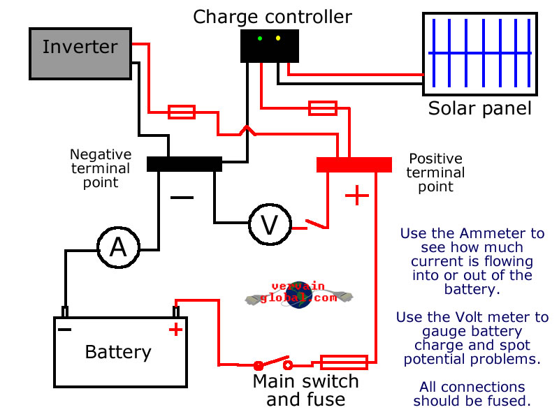
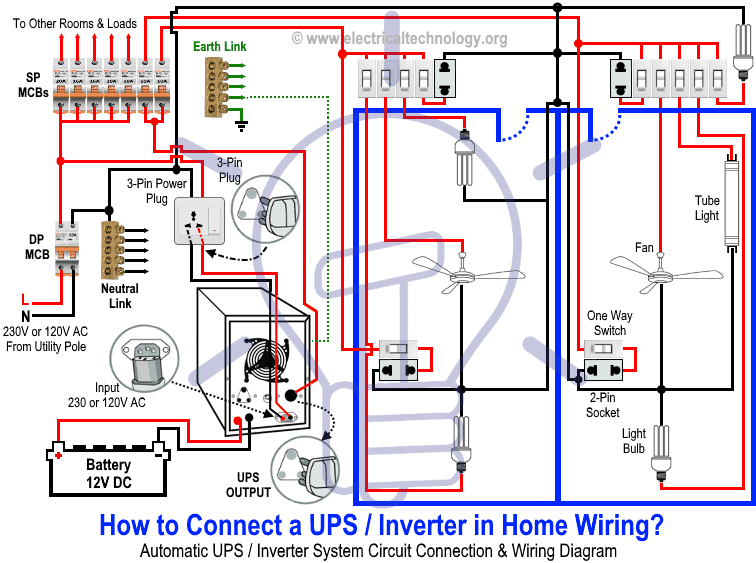
In the below ups wiring diagram. Also a two 12 volts 150 watts solar panel shown which is connected in parallel connection.
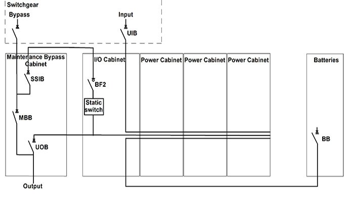
How A Ups Maintenance Bypass Switch Installation Reduces Downtime
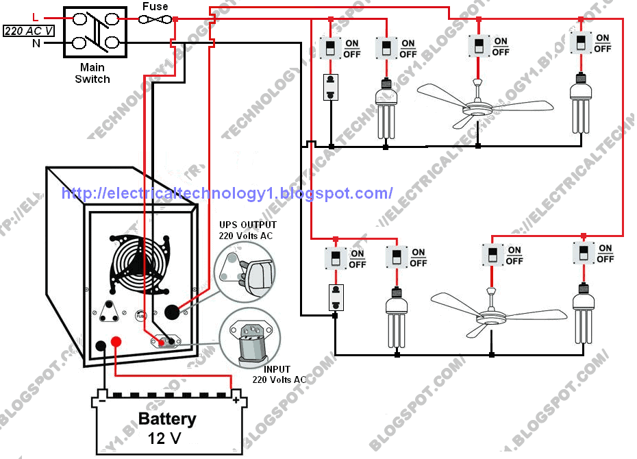
Ups home wiring diagram. Jun 14 2015 how to connect a ups inverter to the switch board. Ups inverter wiring diagram with auto manual changeover switch system. Suppose you have two lighting bulbs one ceiling fan and a 2 pin socket in the first room and one light bulb two calling fans and a 2 pin socket in another room. First we start from ups battery connection. Ups inverter wiring with single additional live wire working and operation of ups connection. Related electrical wiring tutorial.
In the diagram a 12 volt upsinverter shown with battery connection. The circuit drawn pertains to a regular industrial ups uninterruptible power supply which shows how the batteries take control during an outage in electrical supply or variation beyond the normal limits of the voltage line without disruption on the operation providing a steady regulated output 5 volts by lm7805 and an unregulated supply 12 volts. Now if you do this never ever i repeat never ever reverse the polarity of input or output or. Ups power inverter wiring diagram 1 if the above circuit does not work take a piece of wire and connect output neutral of power inverter or ups with neutral wiring of home. The circuit will be closed and appliances will start working. Automatic ups inverter wiring diagram in case of some items depends on ups and the rest on main or generator power.
Automatic ups inverter connections automatic ups inverter wiring with two wires. Ups wiring diagram with solar panel charge controller battery connection and wiring installation for house. Now according to the below ups connection diagram connect an extra wire phase to those appliances where we have already connected phase and neutral wires from power house db ie two wire as phase live as shown in the below fig.


