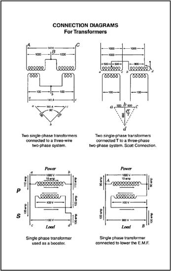
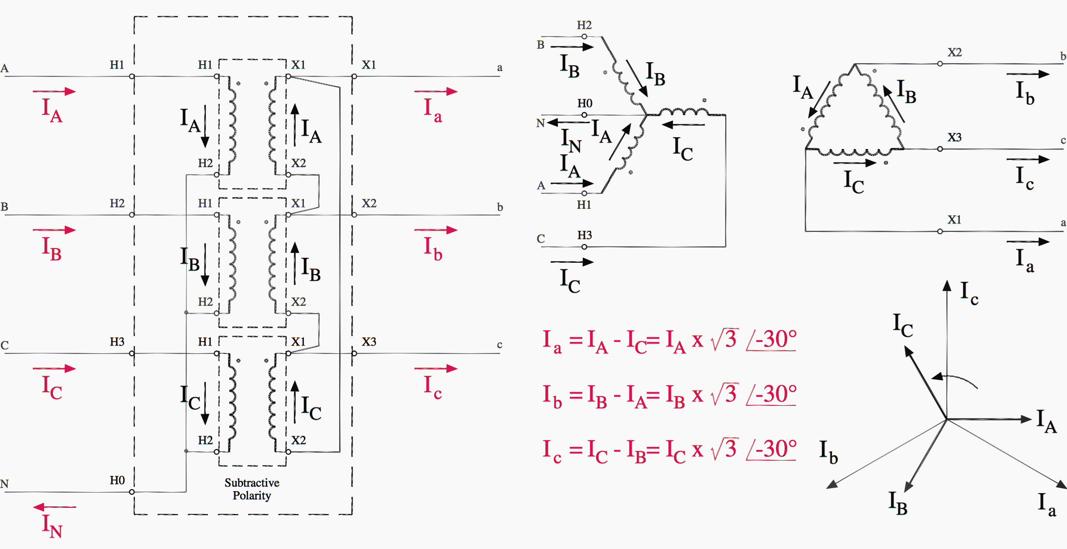
The dashed lines indicate the transformer outlines. The y connection of the three winding transformer is shown in the figure below.
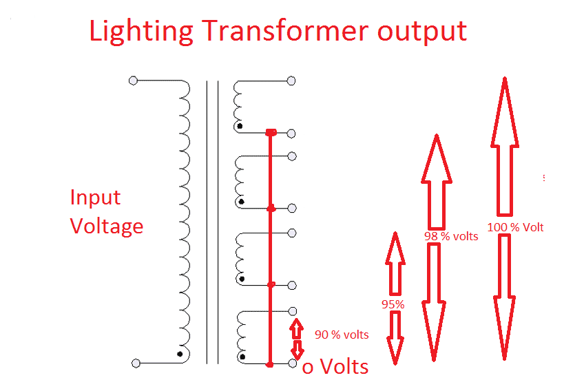
Why Lighting Transformer Used For Lighting Loads Electrical4u
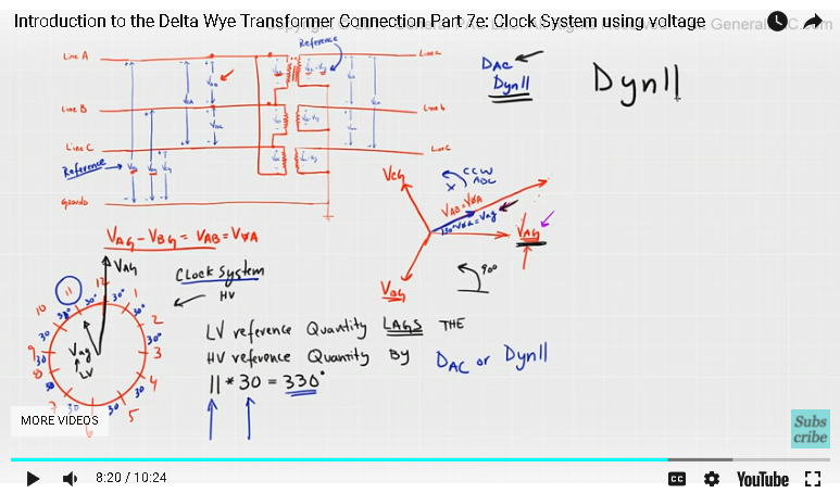
Transformer connection diagram. 480v to 120v transformer wiring diagram elegant 3 phase step down. Star wye delta mesh and interconnected star zig zag. In this case delta side will lag the wye side by 30 0. The combinations of the three windings may be with the primary delta connected and the. Y y y y and. Each transformer is rated as 10 kva current rating is 10 a and voltage rating is 1000 v.
It has primary ad and the secondary b 1 b 2. 480v 3 phase transformer wiring diagram step down tags to 120v. The four basic connections are. In the three phase transformer we can change the transformation by going from star to delta connection. Three phase transformer connection diagram using this method is shown below. The phasor diagram of the y connection of the three phase transformer is shown in the figure below.
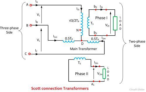
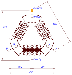
In the case of three phase transformer windings three forms of connection are possible. A three phase transformer is built for a specific connection and voltage transformation and the unit will have a nameplate with the internal connections shown. Step down transformer 480v 120v wiring diagram trusted wiring. The teaser transformer is connected to the line terminal a and the centre tapping d. Or in other words the wye side will lead the delta side by 30 0. The identical interchangeable transformers are used for scott t connection in which each transformer has a primary winding of t p turns and is provided with tapping at 0289t p 05t p and 0866 t p.
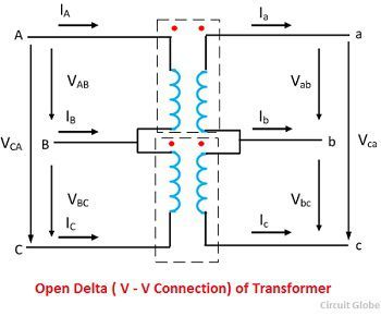
Connection diagram of open delta transformer. The above figure shows the connection diagram of an open delta system. 480v to 240v transformer wiring diagram collections of 480 volt to 120 volt transformer wiring diagram image. Delta closing type dac. The primary and secondary windings of a transformer can be connected in different configuration as shown to meet practically any requirement. The first symbol indicates the connection of the primary and the second symbol is the.
In the case of mixed connections the ratio between the main voltages on the primary and secondary sides is not equal to the ratio between the number of turns. When a single unit or bank of three is used there are four types of connections. This gives us mixed connections. In this diagram a three phase unity pf load resistive load is supplied by two transformers. The connection diagram on the left shows how a deltadelta connection can be made either with three single phase transformers or with one three phase transformer. The figure above shows a delta wye connection with dac connection.
The primary line voltage is equal to the secondary phase voltage. Schematic diagram of a three phase transformer. The relation between the secondary voltages is v ls 3 v ps. Transformer star delta connection diagram the phase voltage is lower than line voltage in star connection so the motors or drives connected in star connection runs at lower speed as compared to.
Gallery of Transformer Connection Diagram