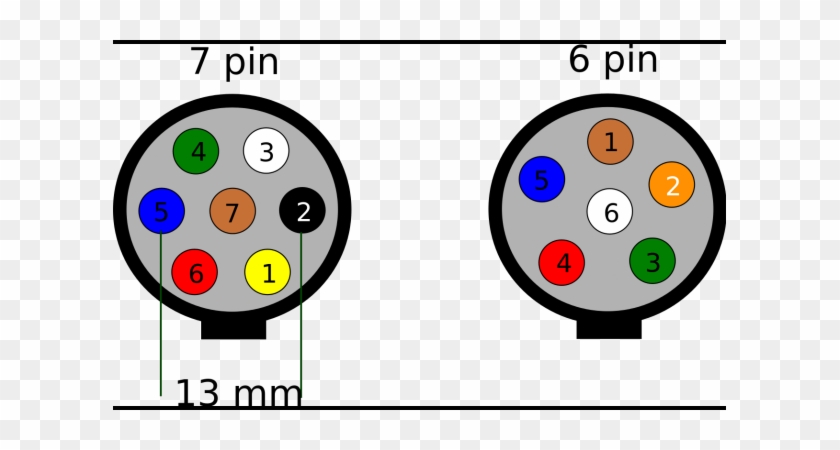
To connect the electric system of your trailer to the vehicle you will be using special connector. This car is designed not only to travel 1 location to another but also to take heavy loads.

Escape City Com View Topic 2011 Escape Tail Light Wiring
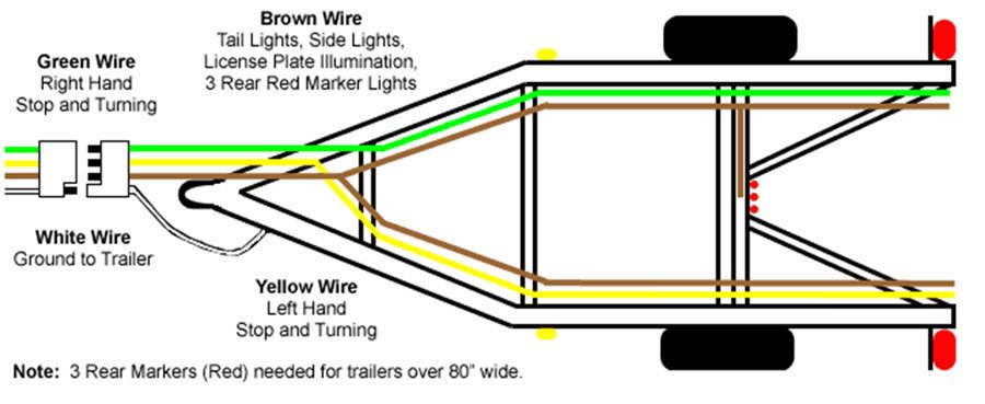
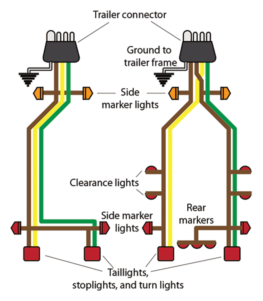
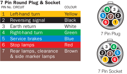
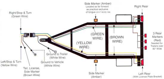
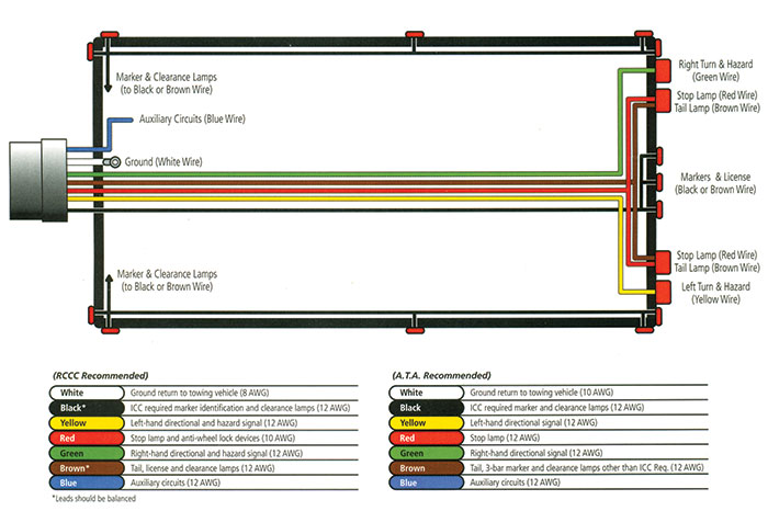
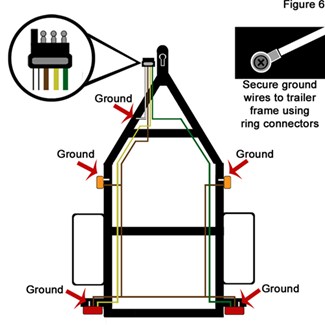
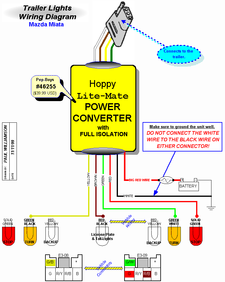
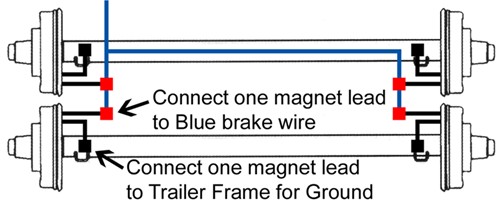
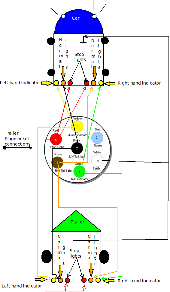
Trailer lamp wiring diagram. 4 pin trailer wiring diagram. This report will be talking trailer lamp wiring diagram. Trailer wiring diagrams trailer wiring connectors. This kit provides a 7 pole rv style trailer connector wiring harness and mounting bracket for adding an aftermarket socketwiring harness includes a 4 color coded 7 wire lead. The trailer wiring diagram above give one flavor for routing direction starting at the tongue connector then wrapping around the trailer. Trailer wiring diagram with electric brakes 7 pin trailer wiring diagram with electric brakes 7 way trailer plug wiring diagram with electric brakes trailer light wiring diagram with electric brakes every electric arrangement is composed of various distinct pieces.
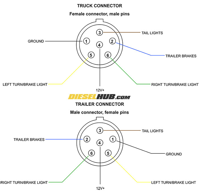
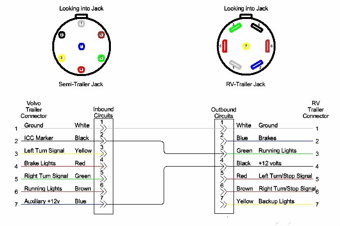
Each component should be set and connected with different parts in specific way. Below is the generic schematic of how the wiring goes. Above we have describes the main types of trailer wiring diagrams. Other people suggest splitting the wires near the tongue then routing down both sides right and left specific. Various connectors are available from four to seven pins that allow for the transfer of power for the lighting as well as auxiliary functions such as an electric trailer brake controller backup lights or a 12v power supply for a winch or interior trailer lights. Gasket prevents leaks when closed has drain slot and angled design for drainage includes wiring diagram for quick installation copper plated terminal pins high conductivity and low resistance sealed.
Trailer lamp wiring diagram narva truck trailer lamp wiring diagram trailer lamp wiring diagram trailer light plug diagram people comprehend that trailer is a vehicle comprised of quite complicated mechanics.

