At room temperature the thermistor offers its nominal value of near 100kω. This turns on the triac controlled heater and also starts the timing cycle.
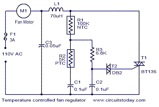
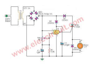
Temperature Controlled Fan Regulator Circuit Automatic Fan
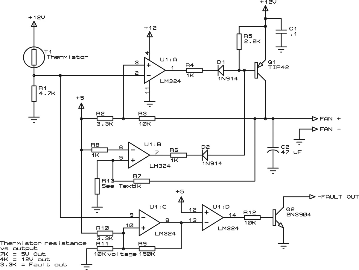
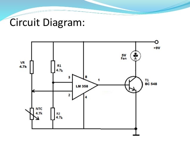
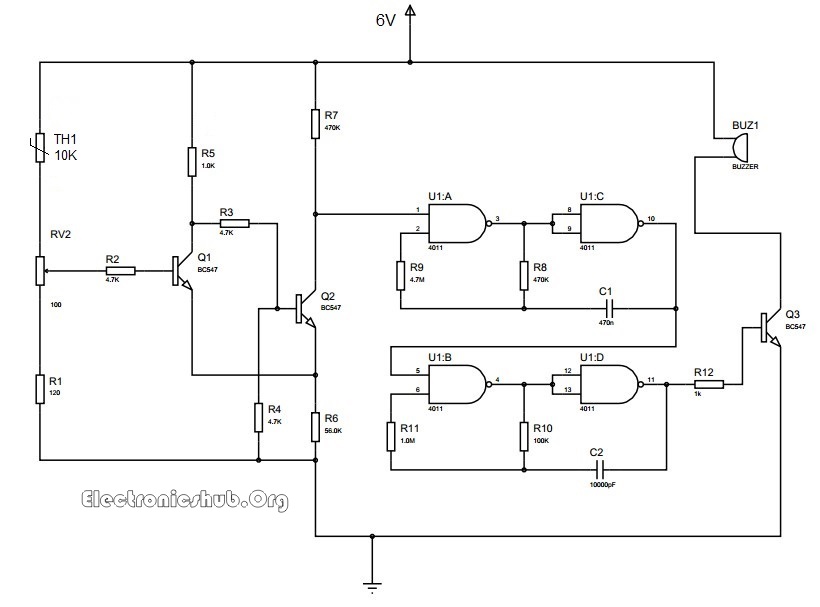
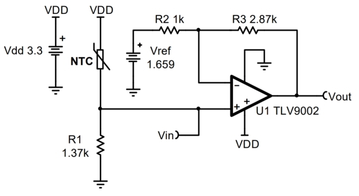
Thermistor based temperature control circuit diagram. The voltage across the thermistor ie. Application of ntc thermistor. 103 is indicating the resistance of thermistor at normal temperature means 10k ohm. This project is designed to develop a temperature control system using a thermistor. The basic working principle of temperature control dc fan is based on the working of the thermistor. At room temperature the voltage across the thermistor will be greater than or equal to the voltage across the resistor.
It is based on the principle of wheatstone bridge. This circuit can be operated on wide range of temperature vary from 5v to 12v. The following figure shows a circuit diagram of temperature controlled dc fan using a thermistor. The frequency of oscillation of ne55 timer depends upon resistor r1 ntc. It works on the principle of thermistor. This circuit uses a negative temperature coefficient ntc as a sensor to sense the heat.
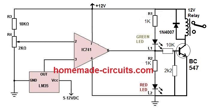
To be able to control any device based on the temperature variation is a very convenient and interesting idea. Here lm358 compares the voltage across the thermistor and the voltage across the resistor. It is helpful to maintain a constant temperature of an enclosed area. The controller has been designed and fabricated using the op amp ic 741 and a 1k thermistor as the temperature sensor. When the thermistor temperature is below a set value the voltage at pin 2 of the 555 drops below 13 of vcc. Heat sensor using thermister is based on a commonly known ic ne555 timer wired in astable mode.
Whenever temperature increases beyond a certain value a lamp indicating a cooler is switched on to bring the temperature to normal. In this circuit pin 3 non inverting terminal of op amp 741 is connected with the potentiometer and pin 2 inverting terminal is connected in between of r2 and rt1 thermistor which is making a voltage divider circuit. Across the arm r4 is compared with the voltage across the variable. The ratio arms r1 and r2 of the bridge are kept fixed say unity. When the temperature increases beyond an exact limit a lamp is switched on to bring the temperature to a normal value. The basic working principle of temperature controlled dc fan is based on the working principle of the thermistor.
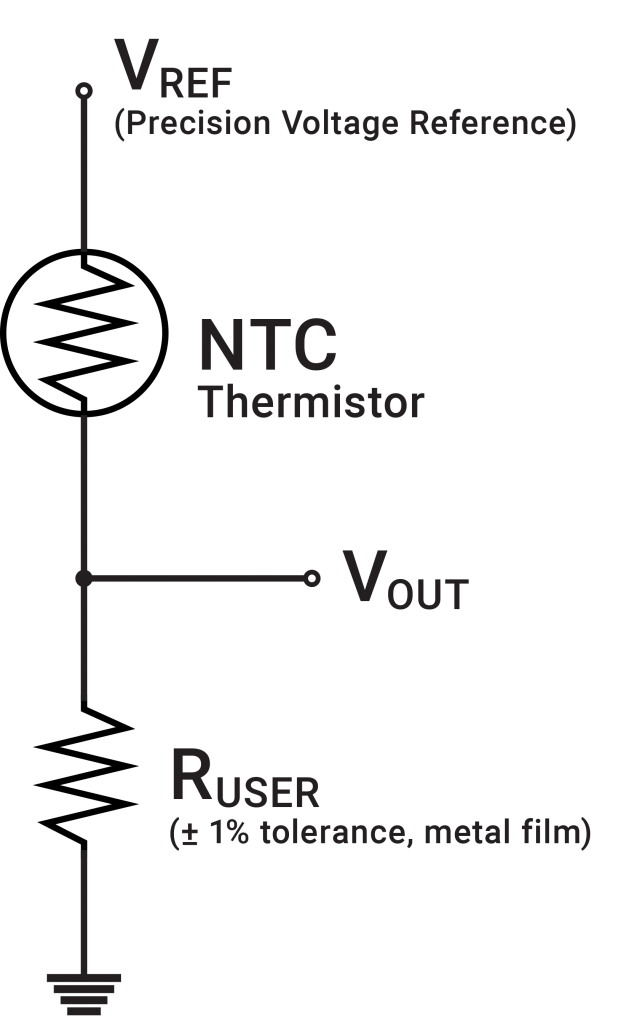
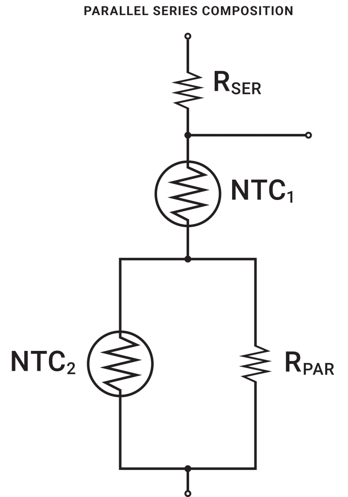
Voltage divides in a voltage divider circuit according to the resistance of each of the components based on ohms law v ir. How this circuit works is we form a voltage divider circuit between the 100kω thermistor and a 50kω fixed resistor. Working of temperature controlled dc fan using thermistor. We are using ntc thermistor in our application. When the temperature. This circuit is connected to the main 220v line therefore it must be handle only by experts.
How does the temperature controller circuit works. The thermistor is a component which changes its resistance as its temperature changes. The main aim of this project is to design a circuit to control a load automatically using a thermistor sensor with a fixed temperature limit. Thermistor based temperature control.

