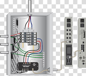
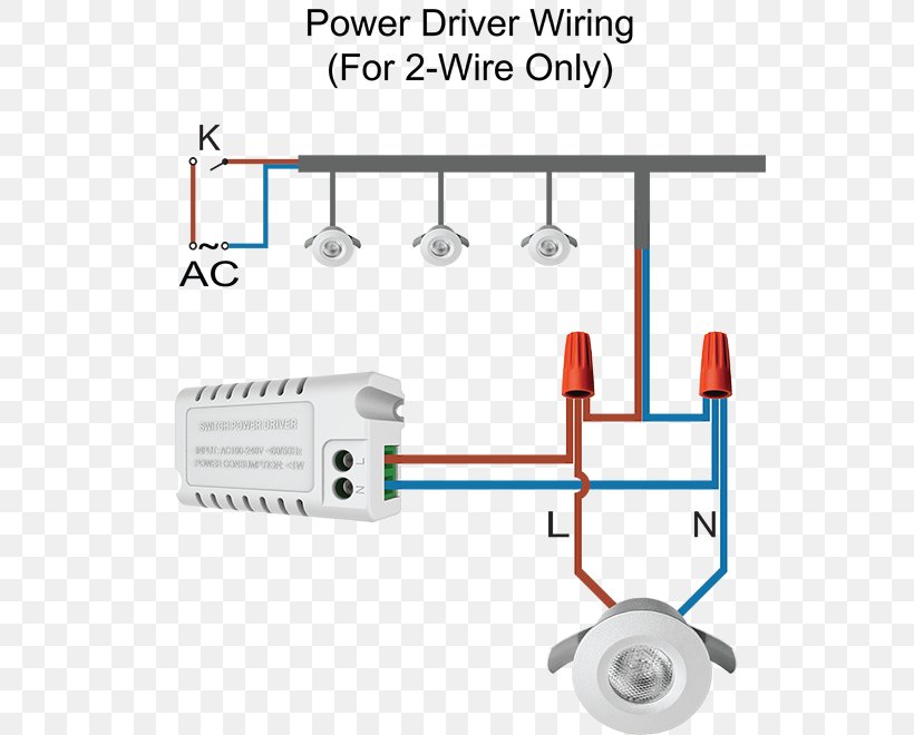
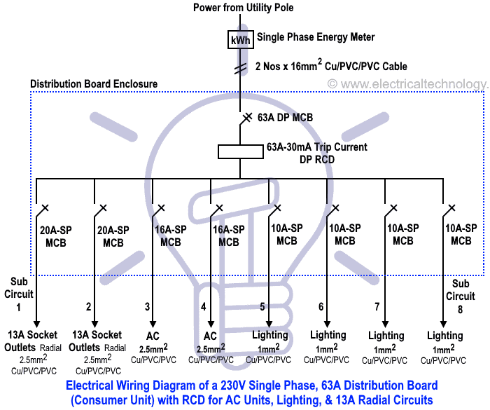
Just a view of the inside backing board of a domestic switch board here in sydney australia. As can be seen in the diagram the wiring is pretty simplethe phase is invariably applied to one terminal of the switch the other terminal moves to one of the connections of the load and the other.

Make Your Own Extension Board 13 Steps With Pictures
Switch board wiring diagram. Multiple light wiring diagram. Wiring diagram of single phase distribution board with rcd in nec us iec uk eu electrical wiring color codes double pole mcb dp the isolator or main switch this is the main operating switch which is used to control the electric power supply in the buildings. This diagram illustrates wiring for one switch to control 2 or more lights. How to wire a switch and a load a light bulb to an electrical supply. It shows how the electrical wires are interconnected and can also show where fixtures and components may be connected to the system. Designing home wiring layouts.
The hot and neutral terminals on each fixture are spliced with a pigtail to the circuit wires which then continue on to the next light. Typical australian domestic switch board domestic switchboard wiring. Electric board wiring connection socket switch indicator lampfusefan pointlighting point 7 way board please subscribe my new channel electricalelectronics diagram. The source is at sw1 and 2 wire cable runs from there to the fixtures. The following explanation will help you understand better how to design home wiring layouts. Inspection of the switchboard is not part of a pre purchase building inspection as per our australian.
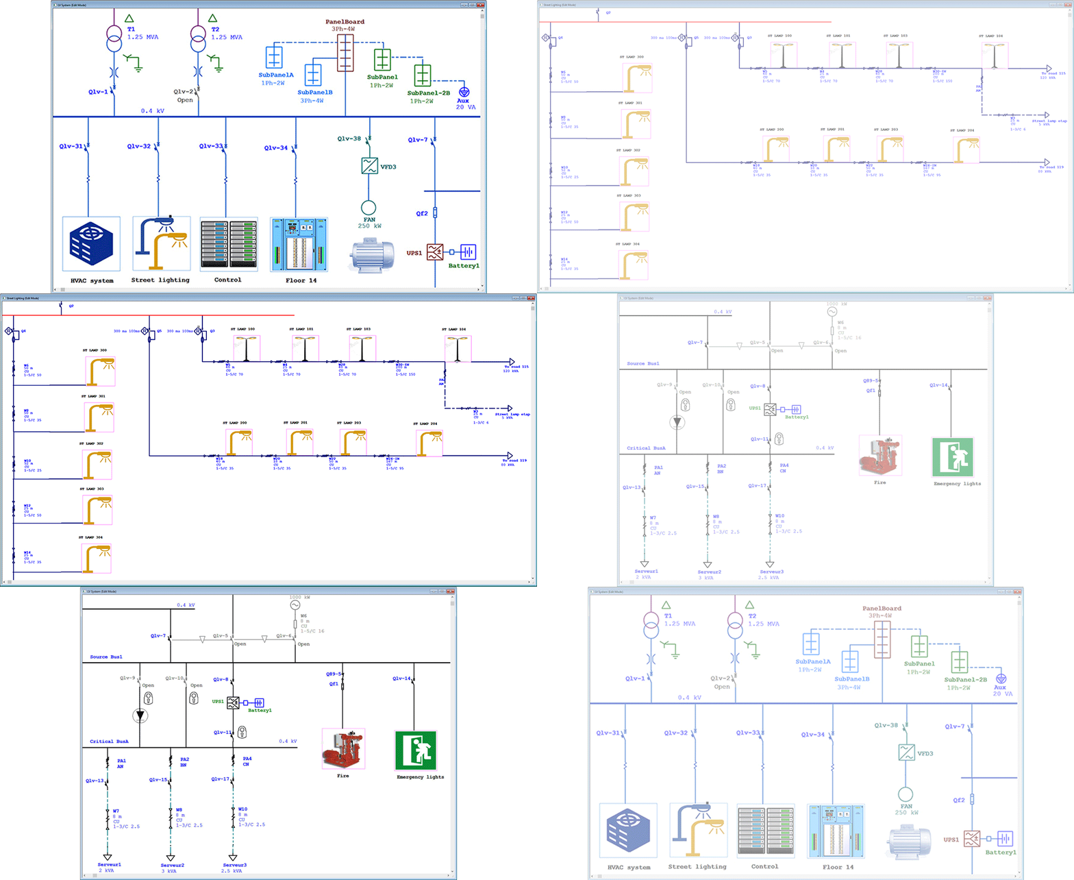
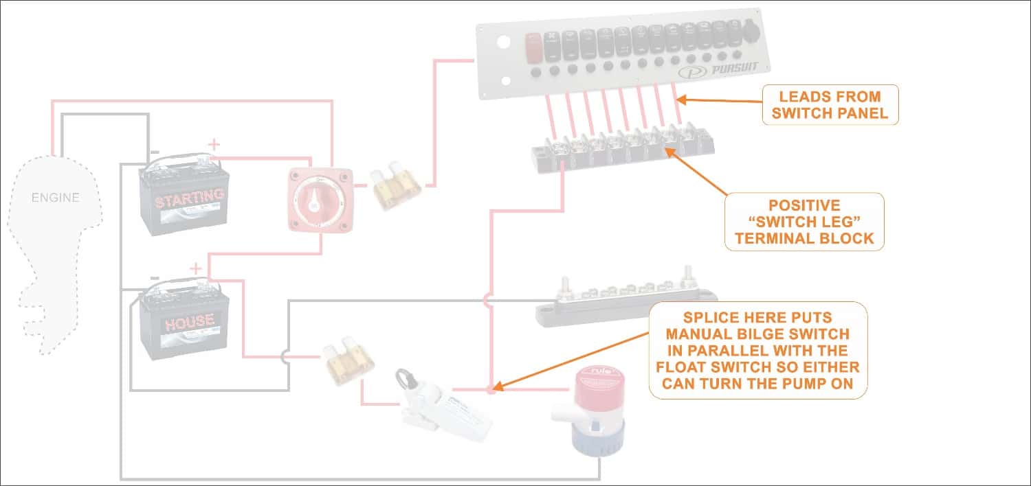
A wiring diagram is a simple visual representation of the physical connections and physical layout of an electrical system or circuit.


