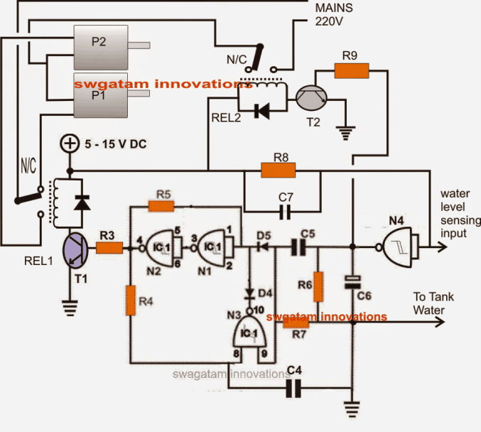
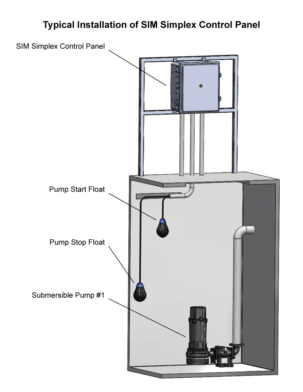
The submersible motor pump starter and automatic panels manufactured by us also protect the pump against against dry run protaction high low voltage protection etc. Rectified dc voltage is regulated to 5v using ic1 and fed to mcu circuit.

Cp02 Dual Pump Control Panel Abs Polycarbonate Box
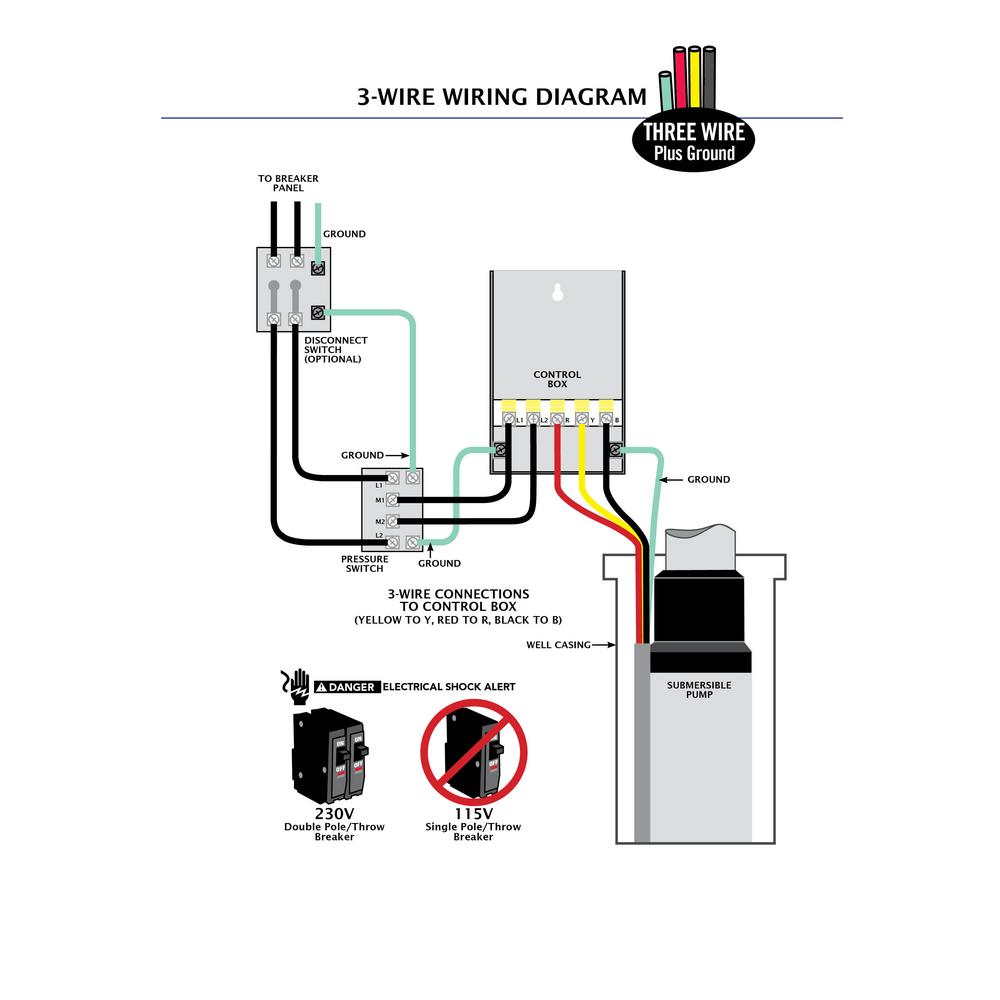
Submersible pump control panel circuit diagram pdf. The circuit is powered with 230v ac mains. 29 best submersible pump images on pinterest. Diodes d1 and d2 act as rectifier diodes and capacitors c1 and c2 are connected as filters. Our submersible pump control panel single phase are specially designed to protect submersible and mono block pumps from over loading and short circuit. In which i control a three phase submersible pump motor using magnetic contactor. 3 wire submersible pump wiring diagram wellread.
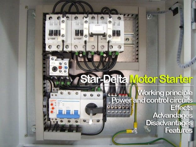
Not only a contactor but also i install the thermal overload relay which will protect the motor form burning in case of over current flow to the circuit. Single phase submersible pump control box wiring diagram 3 wire submersible pump wiring diagram in submersible pump control box we use a capacitor a resit able thermal overload and dpst switch double pole single throw. The wiring connection of submersible pump control box is very simple. Single phase submersible pump motor control box wiring explanation video tutorial. Circuit diagram of submersible motor control panel. Here is the complete guide step by step.
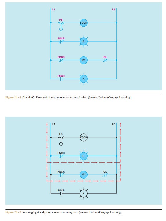
A complete guide about single phase submersible motor starter wiring diagram explanation or single phase 3 wire submersible pump box wiring diagram in english video tutorial. Single phase submersible pump starter wiring diagram gallery amazing single phase water pump control panel wiring diagram frieze. Here is the complete diagram of single phase submersible pump starter wiring diagram below. The above diagram is a symbol diagram here is another diagram from which you can also learn easily so for better understand or if did not understand then watch the below. 1 111213 page 27 control box wiring diagram cb1456c b1463 l1 460 vac three phase wiring external 3 phase connections 460 vac power source circuit breaker red white black l1 l2 l3 green ground g on indicator lamp m a2 a1 43 2 3 4 1 stop float switch start float. Transformer x1 steps down voltage to 9v 0 9v.
Single phase wiring diagrams single phase wiring diagram for 05hp pumps with governor switch single phase wiring diagram with governor switch single phase wiring diagram without governor switch three phase wiring diagrams three phase 208v wiring diagram three phase 230v wiring diagram three phase 460v wiring diagram three phase 575v wiring diagram kb pump wiring diagrams kb pump 230v wiring. 3 phase submersible pump wiring diagram. St4st6 series submersible pumps operation and parts manual rev. Single phase submersible motor starter wiring diagram explanation. Jun 19 2017 single phase 3 wire submersible pump control box wiring diagram or single phase submersible pump starter wiring diagram and wiring installation guide.
