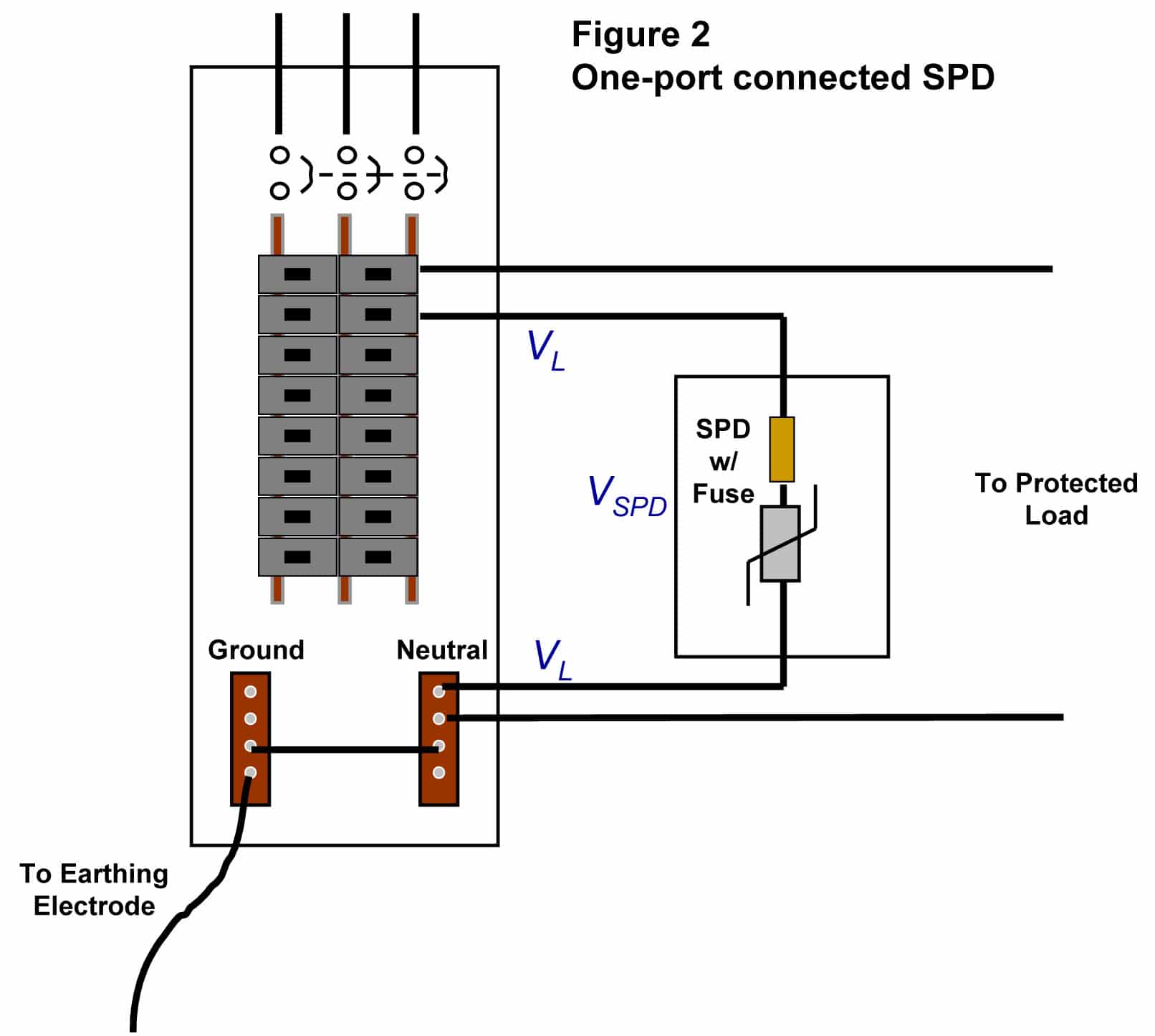
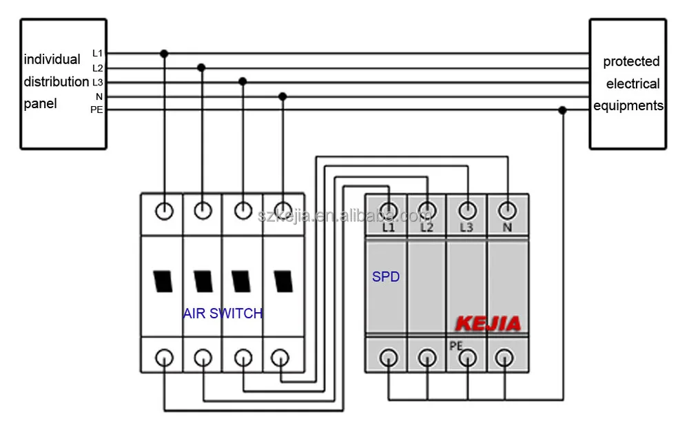
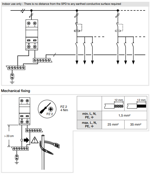
Halving the length of connecting wires halves the inductance but the thickness would have to be increased tenfold to achieve the same effect. This device is connected in parallel on the power supply circuit of the loads that it has to protect see fig.

Surge Protective Device Wiring Diagram H1 Wiring Diagram
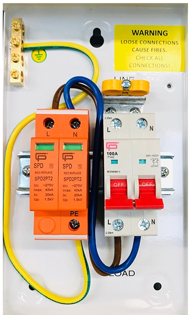
Spd device wiring diagram. Box after wiring is completed using drywall anchors. J17it can also be used at all levels of the power supply network. Locate the spd as close as possible to the circuit being surge limited to minimize the wire length and optimize spd performance. Midnite solar inc. There are three different types of surge protective devices. Wiring single phase units 230 l figure 8.
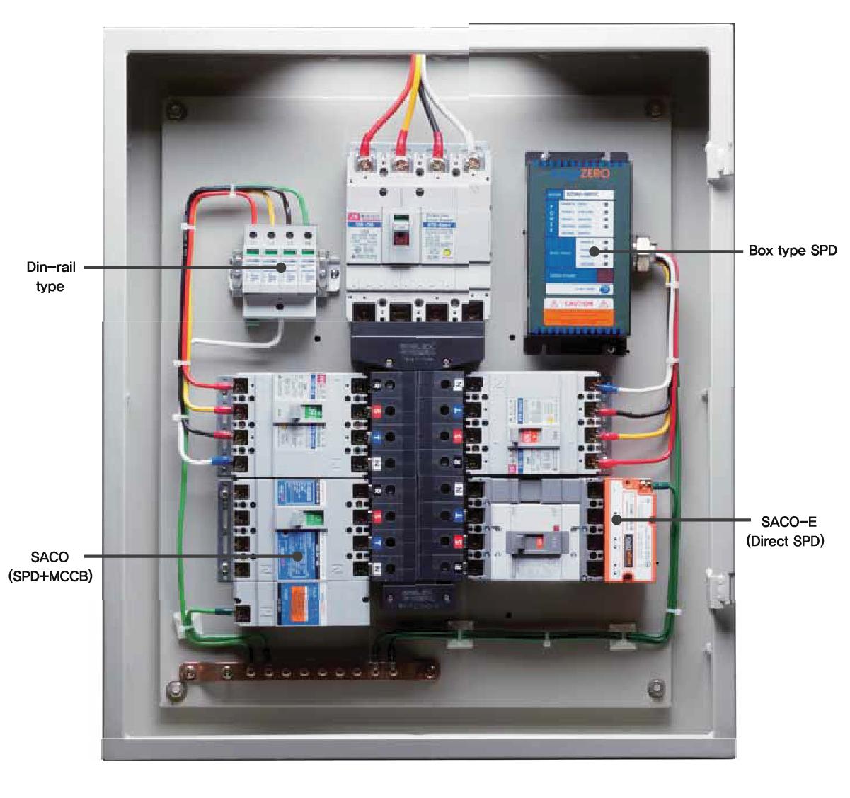
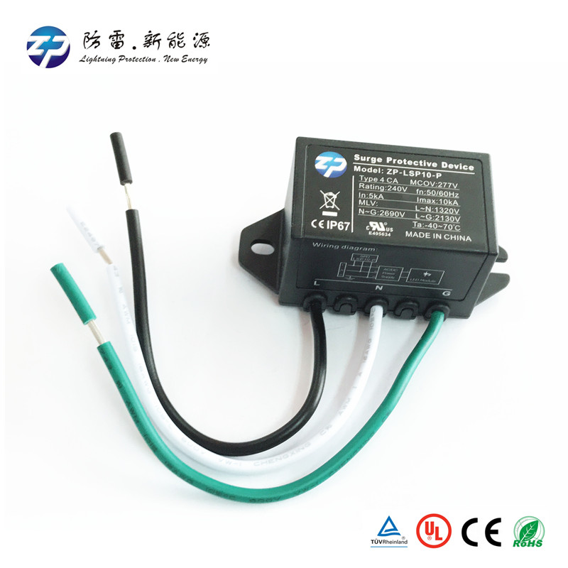
Type 3 spd installed close to the protected load. Wiring 3 phase delta units figure 7. The surge protection device spd is a component of the electrical installation protection system. To reduce the impedance. Type 2 spd installed at sub distribution boards combined type 1 2 spds are available and are usually installed in consumer units. Type 1 spd installed at the origin eg.
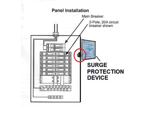
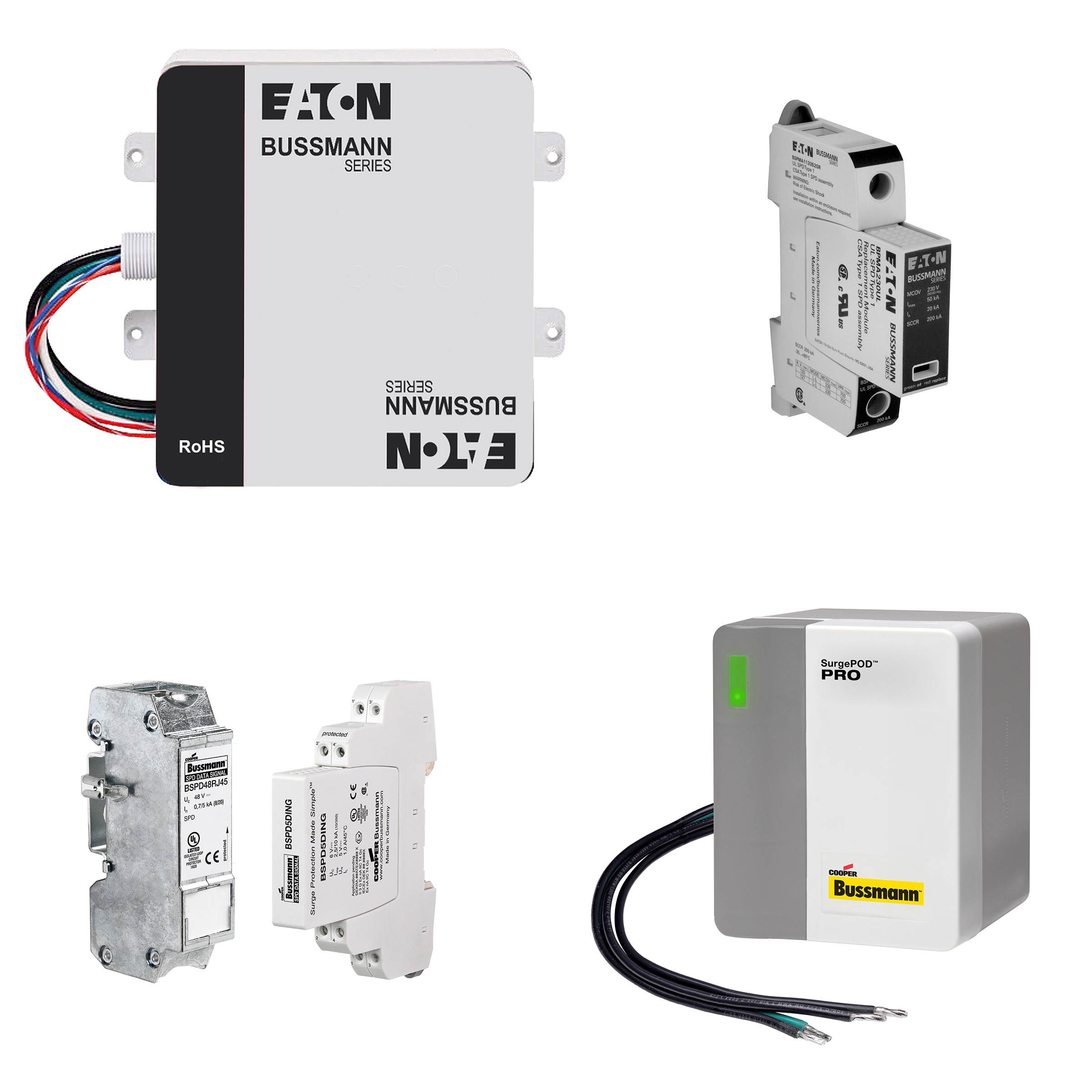
Select the correct wiring diagram for the spd you are install ing. Device spd install spds on the load side of the main overcurrent protection to comply with nec article 285 for type 2 spd. Page 6 eaton spd series instruction manual im01005019e rev. Self inductance of wiring is proportional both to its length and to the logarithm of its thickness. You must refer to this diagram while wiring the spd. Avoid long wire runs so that the device will perform as intended.
Make sure to grommet the hole in the distribution box. Midnite solar surge protection device spd midnite solar inc. Spd performance is a function of the connecting lead length. 5 surge protective device for integrated units effective november 2013 figure 6. Warrants to the original customer that the spd products shall be free from defects in materials and workmanship for a period of five 5.
