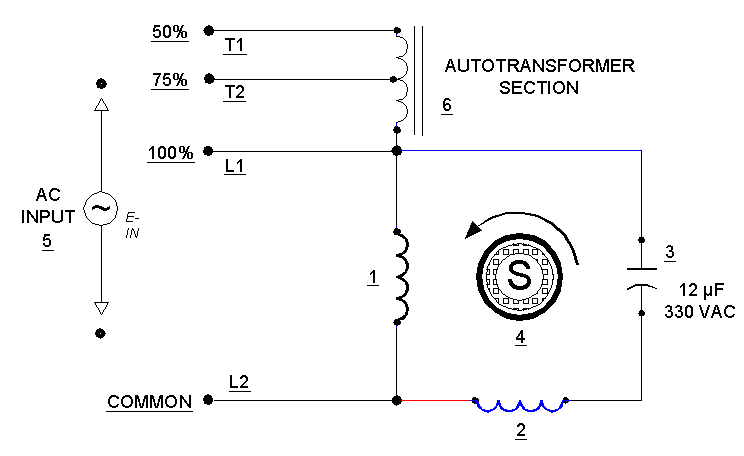
Here is a video on how to wire a single phase three speed alternating current blower motor for another purpose. With the motor disconnected from the load the speed will be close to 1500 rpm regardless of the connection.
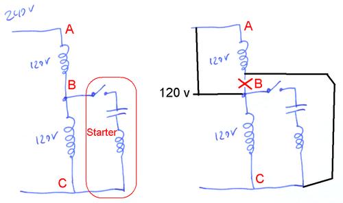
Switching A Motor Between 240 And 120 Volts
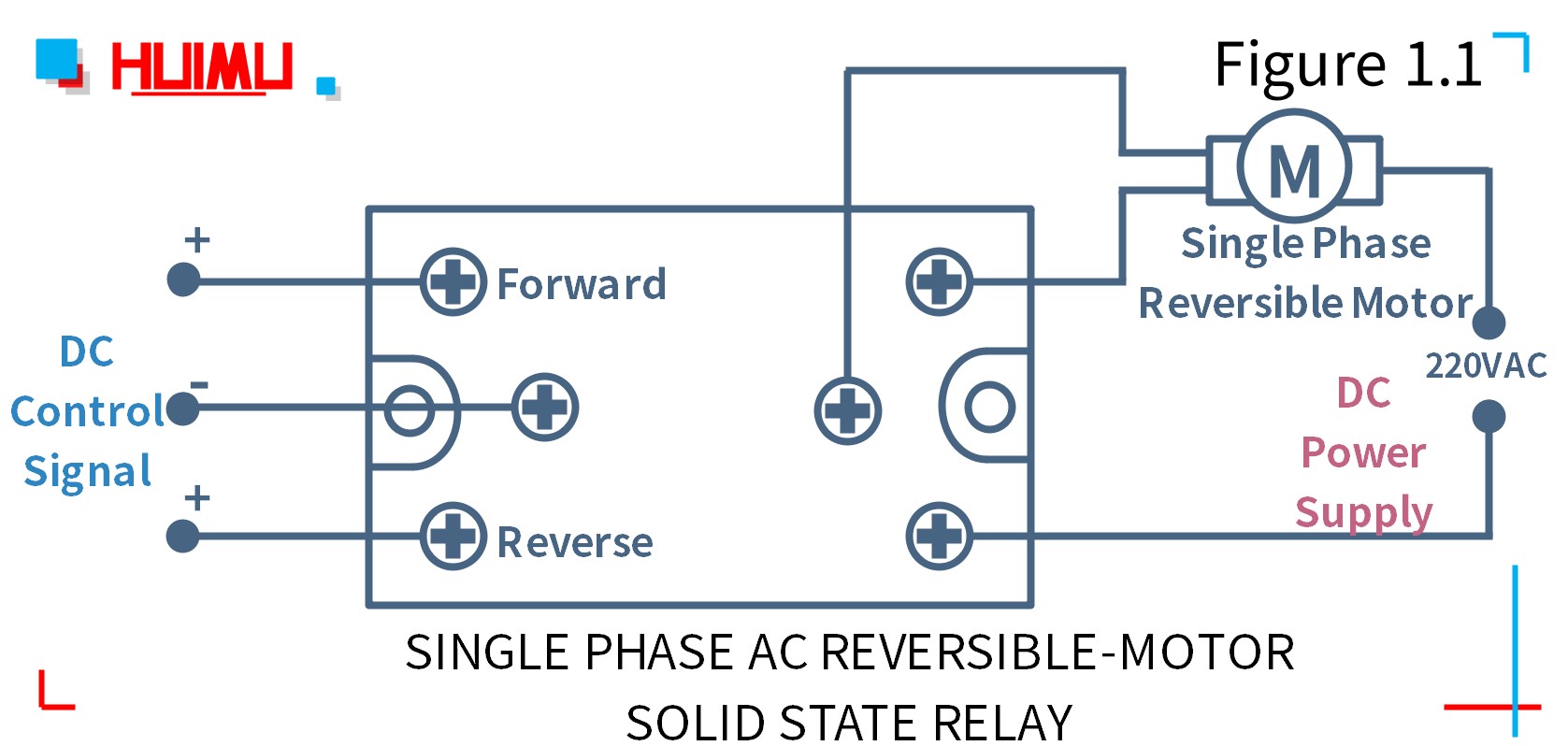
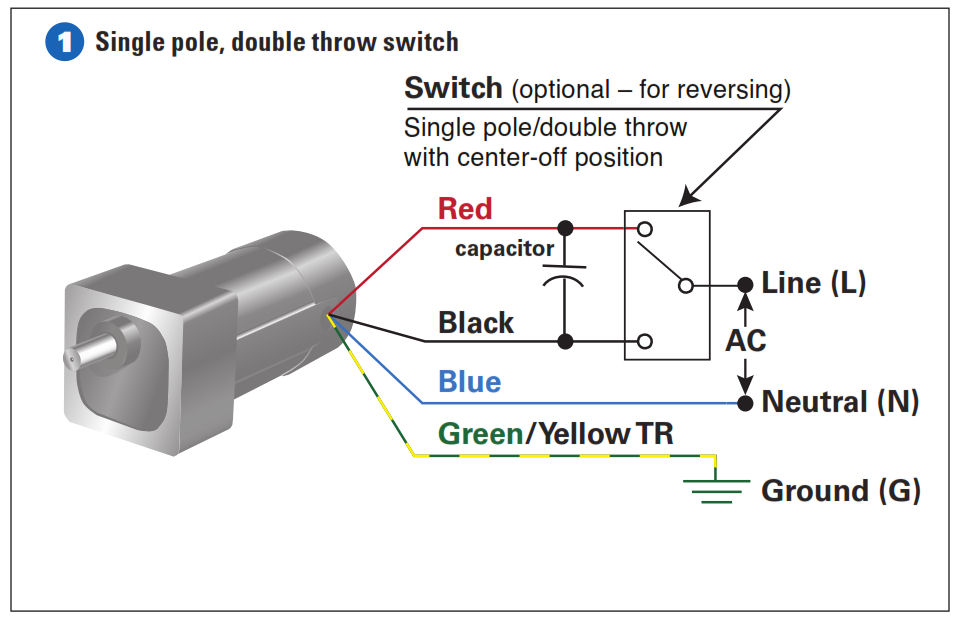
Single phase 3 speed motor wiring diagram. One more thing to keep in mind is that the actual operating speed for a motor like this is determined by the load. If all that is correct the diagram below would be the complete connection diagram. The above diagram is a complete method of single phase motor wiring with circuit breaker and contactor. Learn how a capacitor start induction run motor is capable of producing twice as much torque of a split phase motor. A motor with a start and run capacitor and a start and run coil. In the above one phase motor wiring i first connect a 2 pole circuit breaker and after that i connect the supply to motor starter and then i do cont actor coil wiring with normally close push button switch and normally open push button switch and in last i do connection between capacitor.
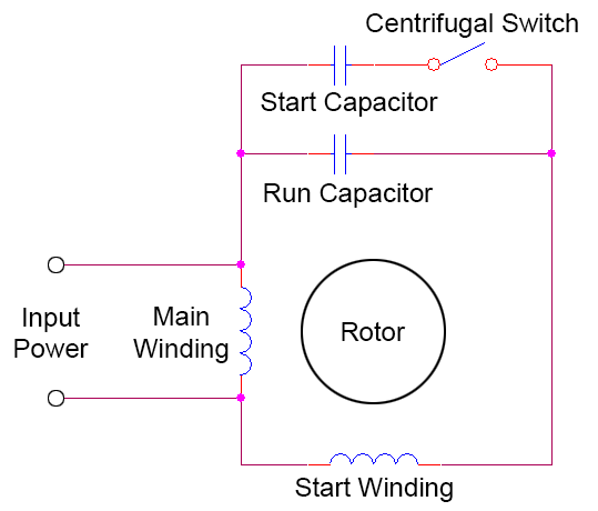
Also read about the speed torque characteristics of these motors along with its different types. Wiring a 3 speed blower motor cool stuff guys like. Diagram dd6 diagram dd7 m 1 ln e diagram dd8 ln e l1 l2 l3 sc z1 u2 z2 u1 cap. Diagram dd6 diagram dd8 m 1 ln e diagram dd9 m 1 ln e white brown blue l1 l2 n sc bridge l1 and l2 if speed controller sc is not required diagram dd7 ln e l1 l2 n sc z2 u2 z1 u1 cap. A split phase capacitor start electric motor may be defined as a form of split phase motor having a capacitor connected in series with the auxiliary winding. This video will show you how to connect a single phase motor with two capacitors.
The load will slow the motor down. Wondering how a capacitor can be used to start a single phase motor. Single phase motor wiring diagram forward reverse single phase motor wiring diagram with capacitor start throughout rh natebird me. Diagram dd5 two speed motors for all other single phase wiring diagrams refer to the manufacturers data on the motor. This wiring is very. Thermal contacts tb white m 1 z2 yellow z1 blue u2 black u1 red bridge l1 and l2 if speed controller sc is not required m 1 ln e.
The auxiliary circuit is opened by the centrifugal switch when the motor reaches 70 to 80 percent of synchronous speed. Diagram dd5 two speed motors for all other single phase wiring diagrams refer to the manufacturers data on the motor. 3 phase motor wiring diagram 9 leads reference wiring diagram for the motor save wiring diagram for single phase how to wire a run capacitor to a motor blower condenser the above illustration does not cover every single type of motor wiring available on the market however motor and capacitor diagram represents a vast. Click here to view a capacitor start motor circuit diagram for starting a single phase motor. Thermal contacts tb white m 1 z2.

