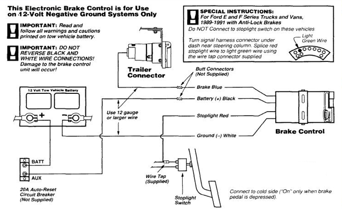
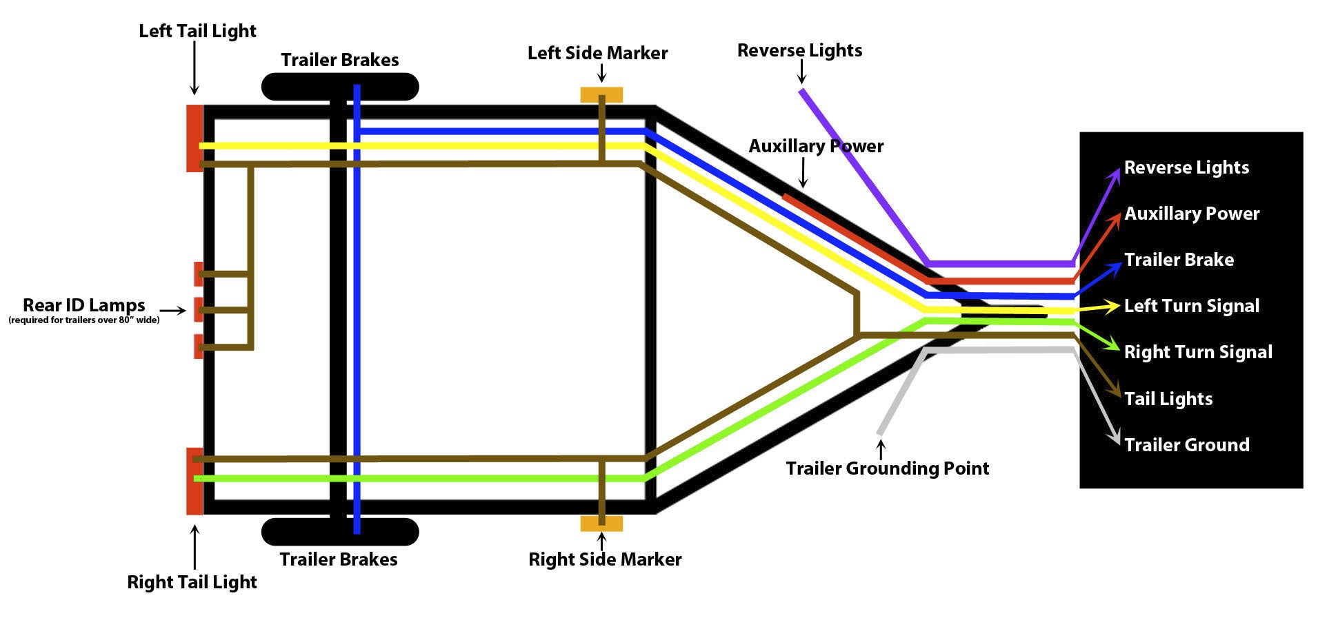
Above we have describes the main types of trailer wiring diagrams. Use the 7 pin connector anyway see below and just leave out the last 2 wires.

Trailer Wiring Diagram Lights Brakes Routing Wires
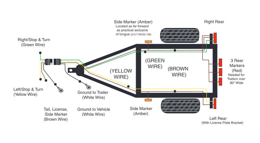
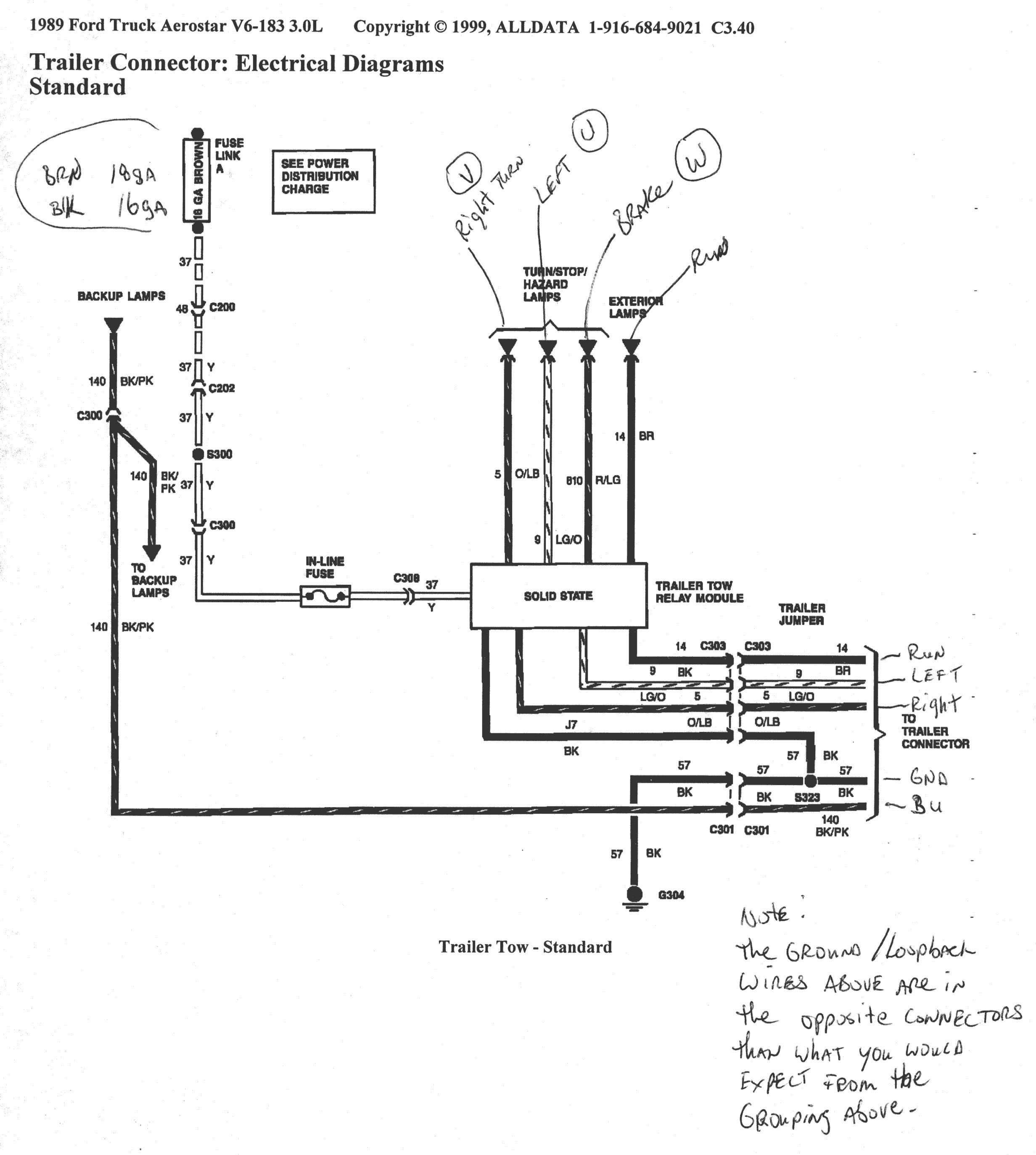
Simple trailer wiring diagram. Complete with a color coded trailer wiring diagram for each plug type this guide walks through various trailer wiring installation solution including custom wiring splice in wiring and replacement wiring. In the trailer wiring diagram and connector application chart below use the first 5 pins and ignore the rest. The remaining wires get installed underneath. If your vehicle is not equipped with a working trailer wiring harness there are a number of different solutions to provide the perfect fit for your specific vehicle. Use this handy trailer wiring diagram for a quick reference for various electrical connections for trailers. Below is the generic schematic of how the wiring goes.
To connect the electric system of your trailer to the vehicle you will be using special connector. The yellow wire powers your left turn signal with green powering the right. Trailer wiring diagram wiring diagrams for trailers international 1 989 755 0561 toll free 1 800 358 4751 covid 19. The white wire is your ground wire which must be cut short and attached to the front of your trailer frame with a screw to power your lights. Use a simple 4 way flat connector to power your 2 light trailer lights or use a custom vehicle specific trailer wiring harness. If your truck has a built in 7 pin socket but you only need 5 of the pins.
Tow vehicle has amber turn signals separate. 4 pin trailer wiring diagram. Has separate bulbs for lighting stop and turn signals both red. Referring to a wiring diagram for a trailer comes in handy during installation.
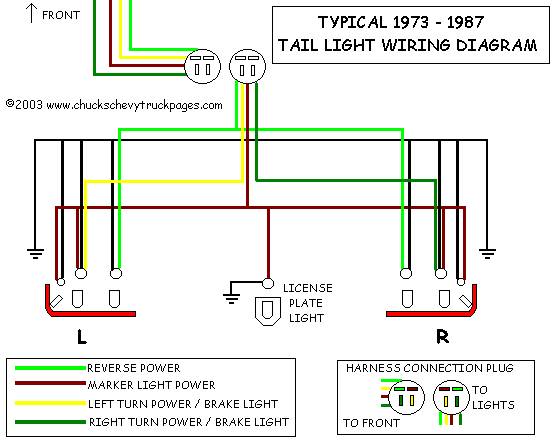


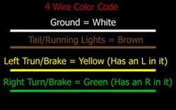
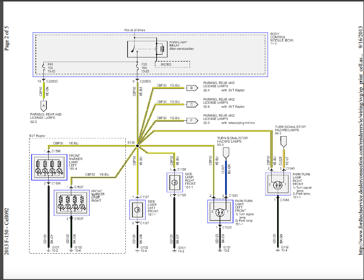

/trailer-wire-colors-589d62645f9b58819cf8721f.gif)
