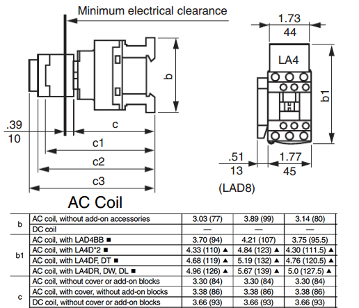
These lines far exceed the 120 volts ac standard in most homes. Approximate dimensions table 14.

230v 3 Phase Contactor Wiring Poli Www Seblock De
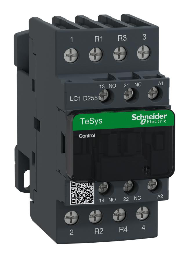
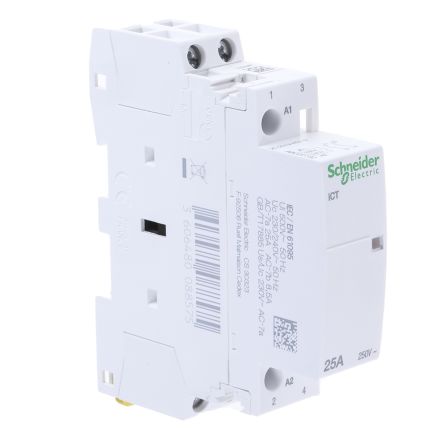
Schneider 3 phase contactor wiring diagram. 2 phase and 3 phase size 00 to 5 44 3 phase size 6 45 3 phase. 1 holding circuit contacts do not come standard. Of poles full load amperes. The main and standbyemergency power supplies the neutrals of the two systems must be separated to assure proper ground fault current sensing. Magnetic contactor wiring diagram single phase. 3 see the instruction label for selection information.
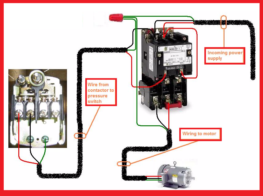
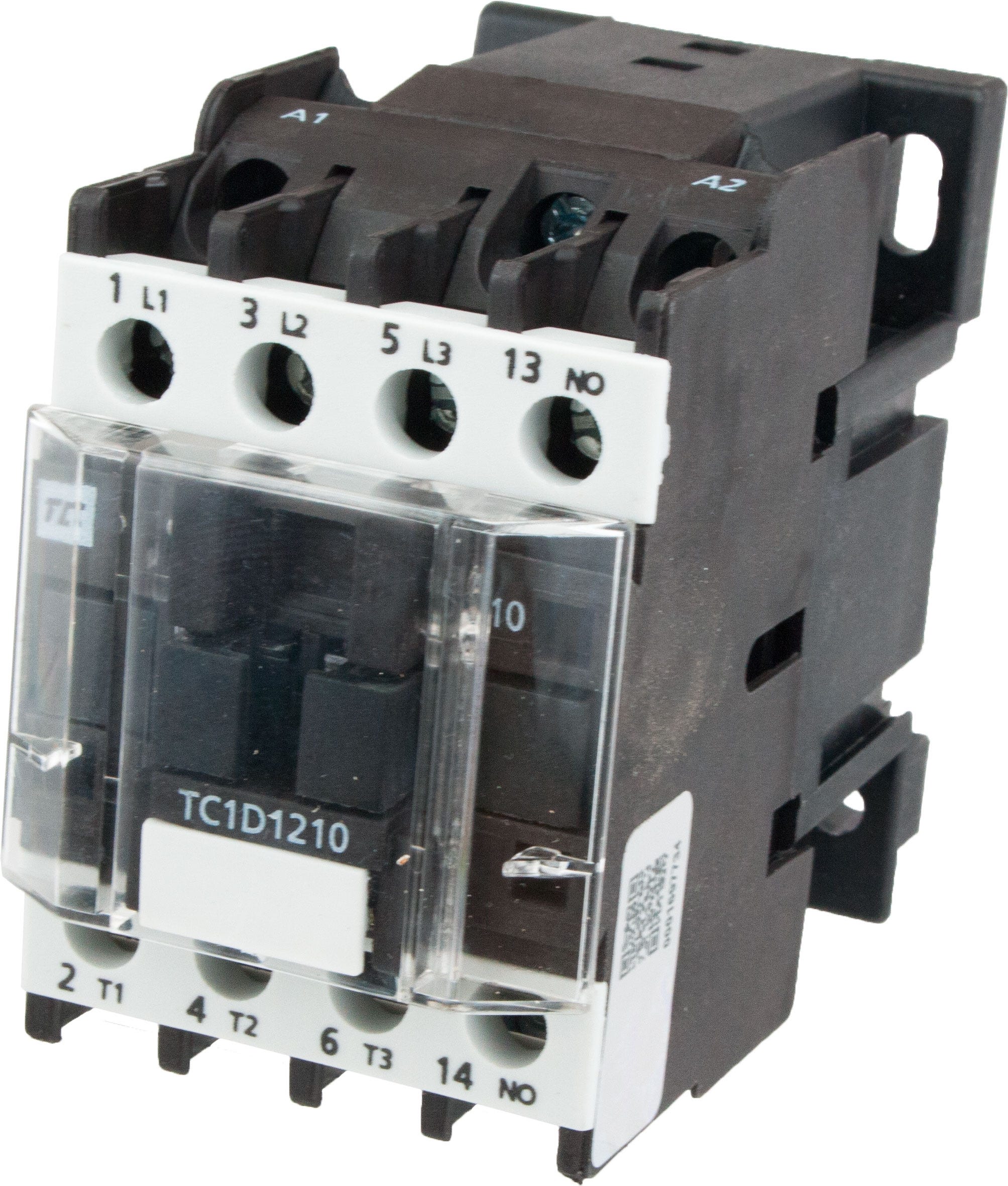
How to wire a contactor. 240 volts ac and 480 volts ac are commonly used for these large pieces of. Refer to the instruction bulletin supplied with the contactor. 3 phase dol starter control and power wiring diagram. Many large pieces of equipment are powered directly from high voltage lines. 2 3 and 4 pole starters600 vac maximum no.
Wiring diagram book a1 15 b1 b2 16 18 b3 a2 b1 b3 15 supply voltage 16 18 l m h 2 levels b2 l1 f u 1 460 v f u 2 l2 l3 gnd h1 h3 h2 h4 f u 3 x1a f u 4 f u 5 x2a r power on optional x1 x2115 v 230 v h1 h3 h2 h4 optional connection electrostatically shielded transformer f u 6 off. Using this method the current is balanced between the 3 poles on the overload. Dol starter control diagram three phase. Dol starter control and power wiring by using a fuse contactor overload relay motor. Ls contactor wiring diagram inspirationa schneider electric wiring diagram for schneider contactor refrence 2 lights 2 switches wiring diagram excel archives noodesign inspirationa wiring. The below wiring diagram shows how we would assemble a complete motor starter with a startstop button for a single phase motor utilizing a 3 pole contactor.
Assortment of schneider electric contactor wiring diagram. Click on the image to enlarge and then save it to your computer by right clicking on the image. Then you connect the 2 motor leads to t1 and t3. Lc1d09p7 tesys d contactor 3p3 no ac 3 440 v 9 a 230 v ac coil. The people providing this information may or may not be providing completely accurate information. Water pump controller with float switch duration.
2 add the voltage code suffix from table 22 on page 10. Wiring diagram for telemecanique lc1 contactor replacements by us breaker lr aux nc1d aux nc1d aux m control supply voltage is the same as the main circuit voltage 3 phase control supply voltage is not the same as the main circuit voltage 3 phase connect to other supply control supply voltage is the same as the main circuit voltage single. Easy and simple wiring diagram to make you learn easily watch the video and subscribe my youtube channel air. Ryb electrical 88232 views.

