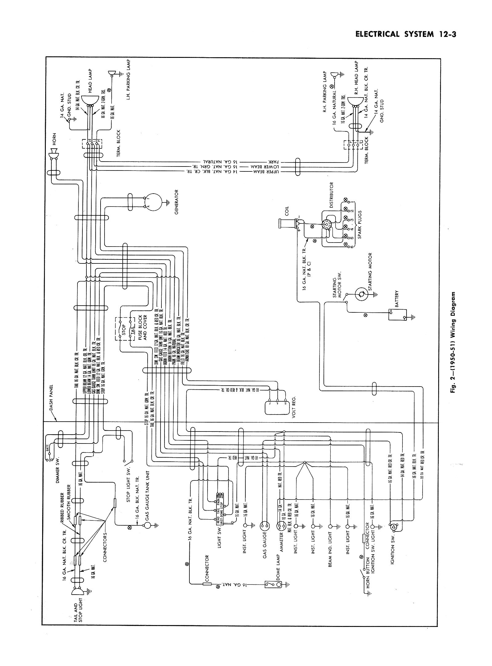
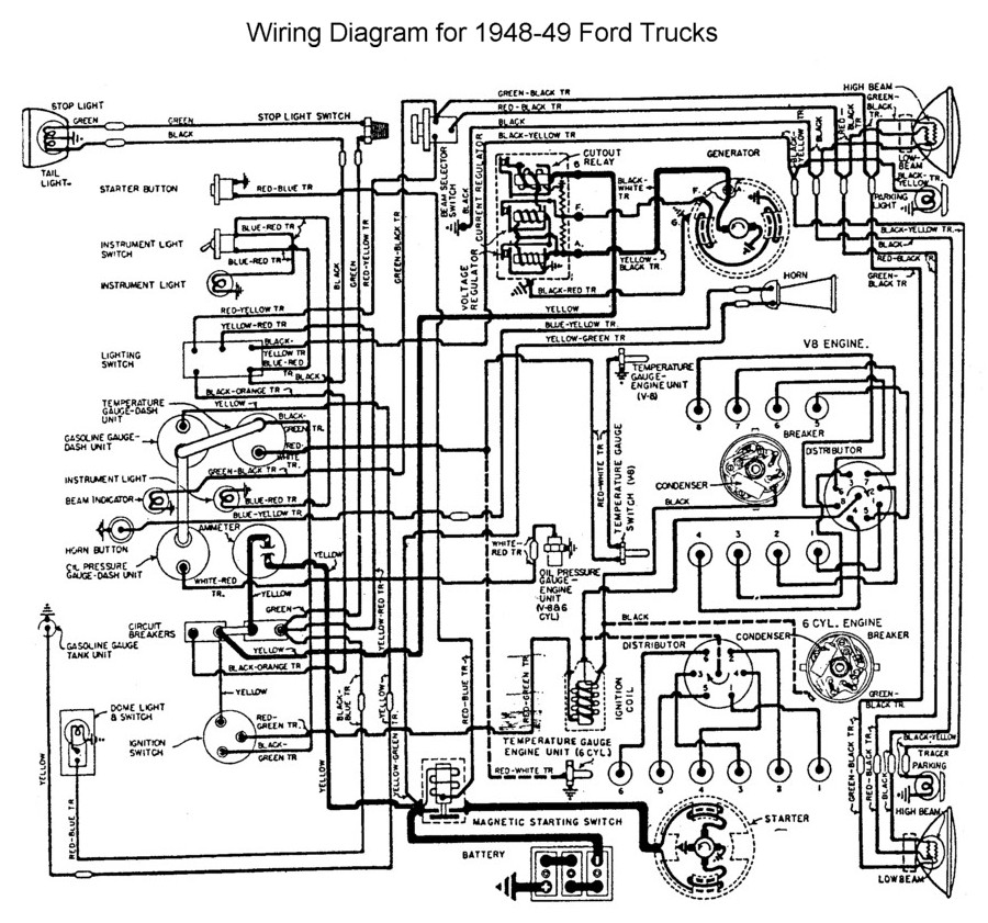
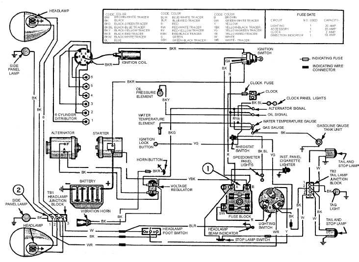
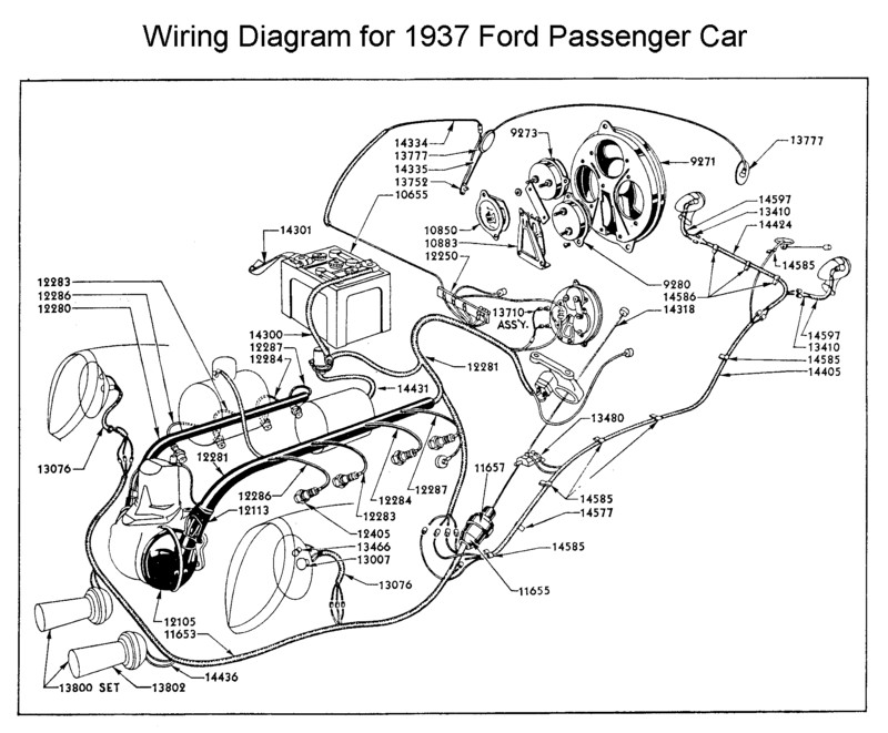
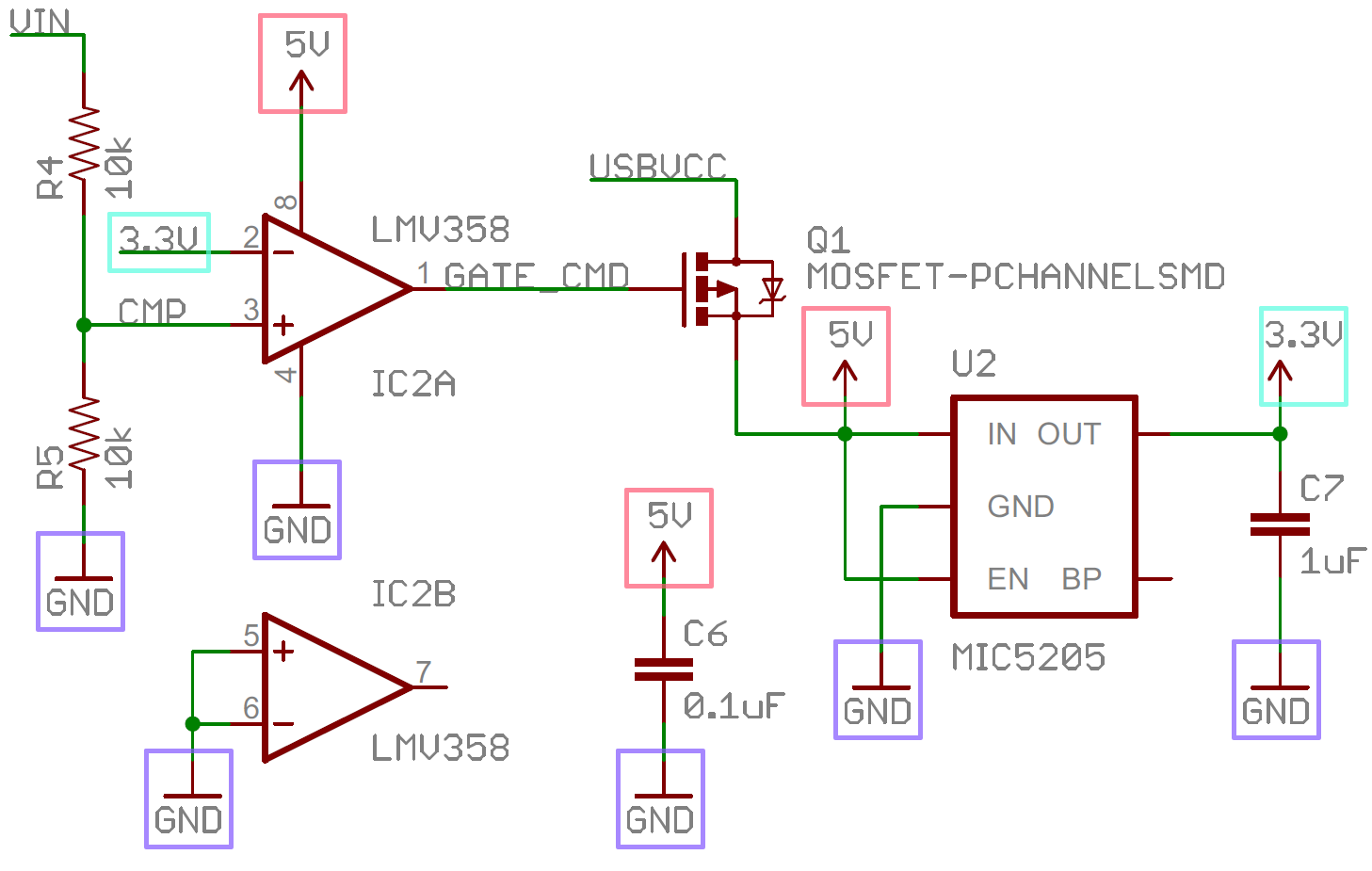
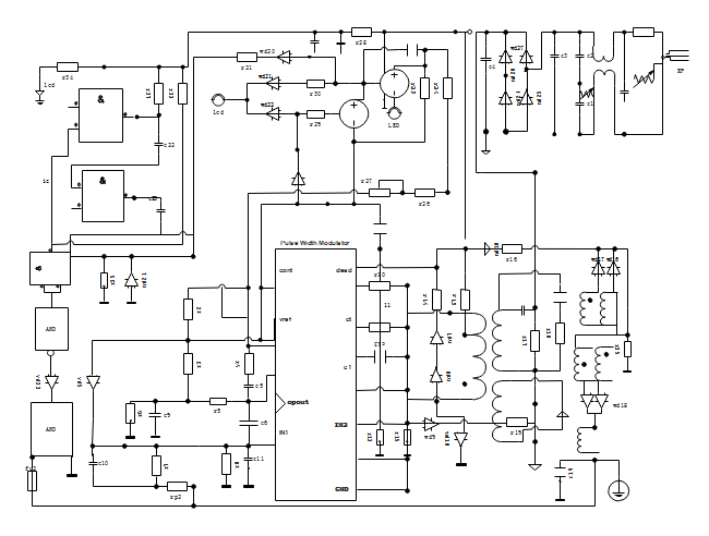
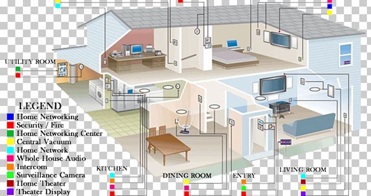
Wiring diagrams show how the wires are connected and where they should located in the actual device as well as the physical connections between all the components. The most fundamental of circuit components and symbols.
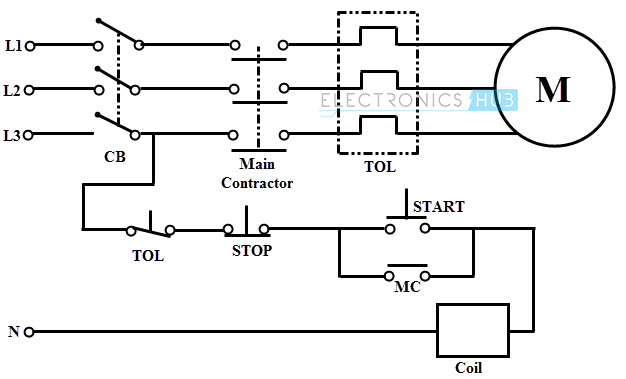
Electrical Wiring Systems And Methods Of Electrical Wiring
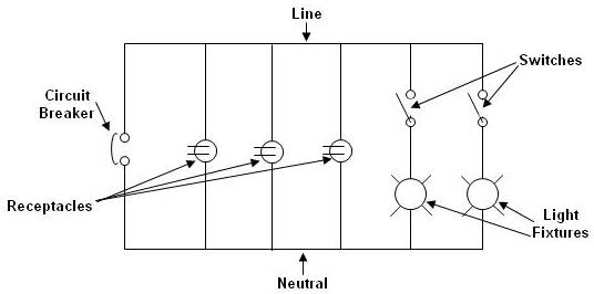
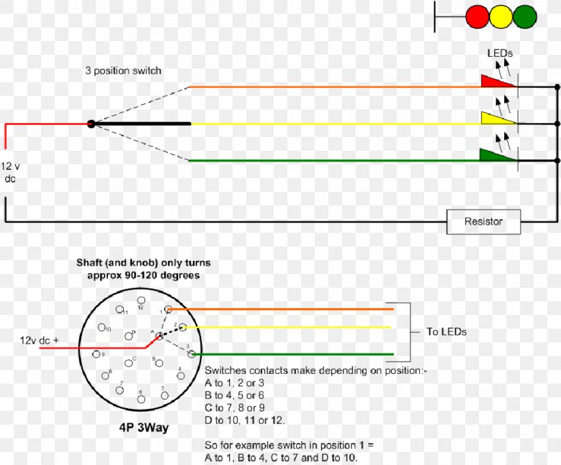
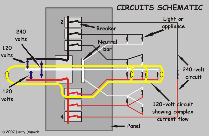
Schematic diagram of electrical wiring. Feb 5 2020 explore elects agass board electrical diagram on pinterest. Figure 4schematic diagram wiring diagram or pictorial. With capacitor marking and installation single phase electrical wiring installation in home according to nec iec. With the light at the beginning middle and end a 3 way dimmer multiple lights controlling a. When looking at any switch diagram start by familiarizing yourself with the symbols that are being used. It is used to show how the circuit functions.
Complete with a color coded trailer wiring diagram for each plug type this guide walks through various trailer wiring installation solution including custom wiring splice in wiring and replacement wiring. If your vehicle is not equipped with a working trailer wiring harness there are a number of different solutions to provide the perfect fit for your specific vehicle. Use the rv electrical diagram we made below to get an understanding of what powers what and to learn how an rv electrical system works. See more ideas about electrical diagram electrical circuit diagram electrical engineering. A diagram that uses lines to represent the wires and symbols to represent components. Wiring diagrams for 3 way switches diagrams for 3 way switch circuits including.
How is a wiring diagram different from a schematic. Wiring diagrams for receptacle wall outlets diagrams for all types of household electrical outlets including. A schematic shows the plan and function for an electrical circuit but is not concerned with the physical layout of the wires. Schematic symbols part 1 are you ready for a barrage of circuit components. Electrical wiring of the distribution board with rcd single phase from energy meter to the main distribution board fuse board connection. Here are some of the standardized basic schematic symbols for various components.
Room air cooler wiring diagram 2. Duplex gfci 15 20 30 and 50amp receptacles. Room air cooler electrical wiring diagram 1. A simplified conventional pictorial representation of an electrical circuit. Rv electrical diagram wiring schematic understanding you campers electrical wiring can be very confusing. The electrical symbols will not only show where something is to be installed but what type of device is being installed.
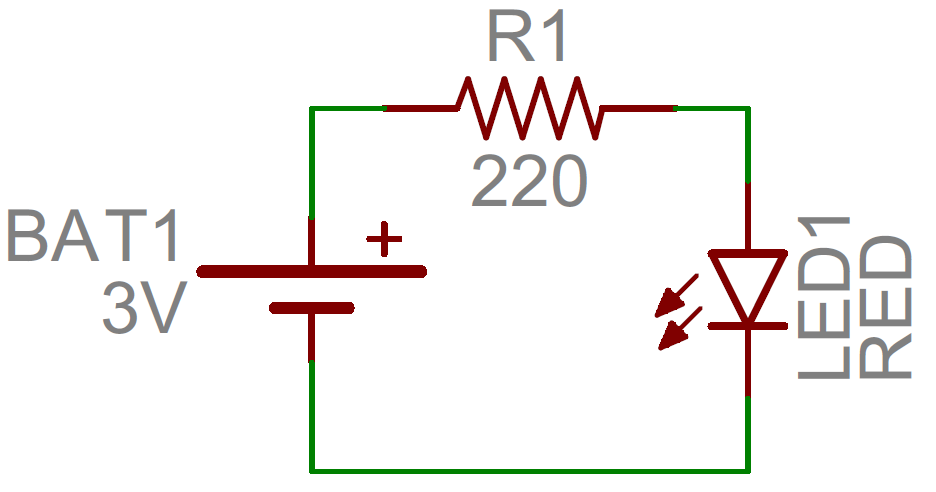
Resistors on a schematic are usually represented by a few zig zag lines with two terminals extending outward.
