Salzer selector switch 20a. Technical information rotary cam switches switching diagrams technical information rotary cam switches switching diagrams salzer selector switch 20a.

Salzer Rotary Cam Switch Wiring Diagram Filterx Down8
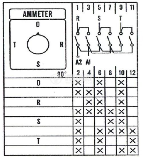
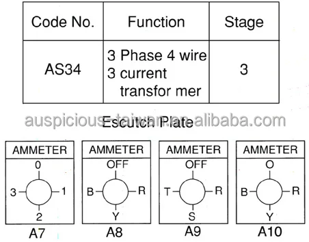
Salzer selector switch wiring diagram. Salzer switches s tp rt series are designed to accomodate two isolated double break silver alloy contacts per stage at 180 degree. 20a 2 these switches have 2 to 8 positions and 1 to 12 stages 3 widely used to change position of ammeter and voltmeter to control the direction of mot. Salzer electronics limited samichettipalayam coimbatore 641 047 india. Technical information rotary cam switches switching diagrams 61045 61062. 61317 61317a 61317b 61317c 61317d 61317e 3 phase line to line for 2 sources. 61313 61313a 61313b 61313c 61313d 61313e 61313f 61313g 3 phase line to line 1 phase line to n 3 5 61317.
61311 61311a 61311b 61311c 61311d 61311e 3 phase line to line 3 phase line to n 3 6 61313. 20a 2 these switches have 2 to 8 positions and 1 to 12 stages 3 widely used to change position of ammeter and voltmeter to control the. Technical information rotary cam switches switching diagrams 61063 61082. Switch type rated uninterrupted current ith a dc 22a lr 2m sec rated operational voltage no of series contacts 110v 250v 460v 1 2 4 a16 25 32 40 63 dc 23a lr 75m sec. Voltmeter selector switches with off 3 phase line to n 2 4 61311. Connecting diagram 1 to 12 pole 1.


