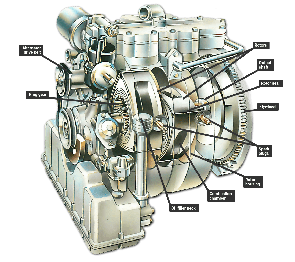
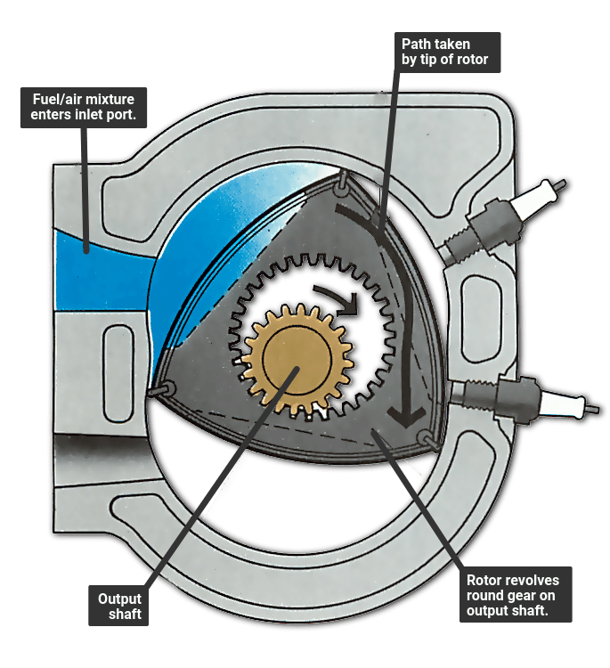
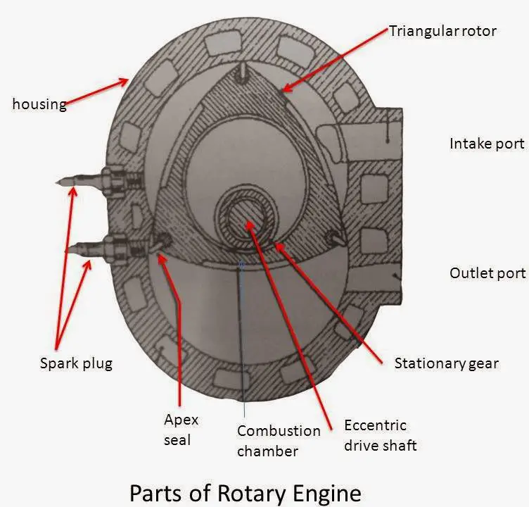
This lobe is offset from the centerline of the shaft and acts like the crank handle on a winch giving the rotor the leverage it needs to turn the output shaft. The heart of a rotary engine is the rotor.

Mh 7480 Rotary Engine Diagram Free Diagram
Rotary motor diagram. The rotor is mounted on a large circular lobe on the output shaft. Check out my website. The prototypes wheels were driven via an electric motor and a 033 liter 38 horsepower rotary engine would spool up to recharge the electric motors batteries if they ran low and there was. The wankel engine is a type of internal combustion engine using an eccentric rotary design to convert pressure into rotating motion. This animation provides a basic understanding of how the rotary engine is put together and how it works. All parts of a rotary engine rotate in one direction.
This is roughly the equivalent of the pistons in a piston engine. Its main application was in aviation although it also saw use before its primary aviation role in a. In contrast to the reciprocating piston designs the wankel engine delivers. The rotary engine was an early type of internal combustion engine usually designed with an odd number of cylinders per row in a radial configuration in which the crankshaft remained stationary in operation with the entire crankcase and its attached cylinders rotating around it as a unit. This is opposed to the common reciprocating piston engine which has pistons instantly and rapidly changing direction 180 degrees. It was created with 3ds max cinema 4d and after effects.
Green red and tan. The motor has a switch housing with 3 wires coming out the housing. 6 thoughts on rotary lift wiring diagram model spoa9a3000.


